
How to Build a Knowledge Graph for Manufacturing Operations
The core and domain ontologies define what may exist in a manufacturing environment. Here we use them to build a knowledge graph of what actually exists.

In the previous articles, we created a core manufacturing ontology and extended it with domain-specific concepts for production, quality, maintenance, inventory, and energy.
The core ontology established the shared semantic structure of manufacturing operations through abstract concepts such as Process, PhysicalEntity, OperationalEntity, Agent, Location, Capability, Role, Event, and State.
The domain ontologies then specialized those concepts into things that are meaningful within particular plant operations: production, maintenance, quality, inventory and energy. At this point, however, we still only have an ontology.
The ontology defines the vocabulary and rules we can use to describe manufacturing operations. It tells us, for example, that a ProductionLine is a type of WorkCenter, that a Warehouse is a type of Area, and that both ultimately belong to the broader concept of Location.
What it does not yet tell us is what actually exists in a particular manufacturing company.
It does not tell us that Global Industries operates plants in Munich and Dallas, that the Munich site contains separate production, packaging, utilities, and raw-material areas, or that its production area contains a line called Line 1.
Those are facts about a specific operational environment.
To create a Knowledge Graph, we begin populating the ontology with instances representing those real-world things and connect them using the relationships defined by the ontology.
In this article, we will create the first instance layer of our manufacturing Knowledge Graph: the plant-location hierarchy for a fictional company called Global Industries.
The Manufacturing Operations Scenario
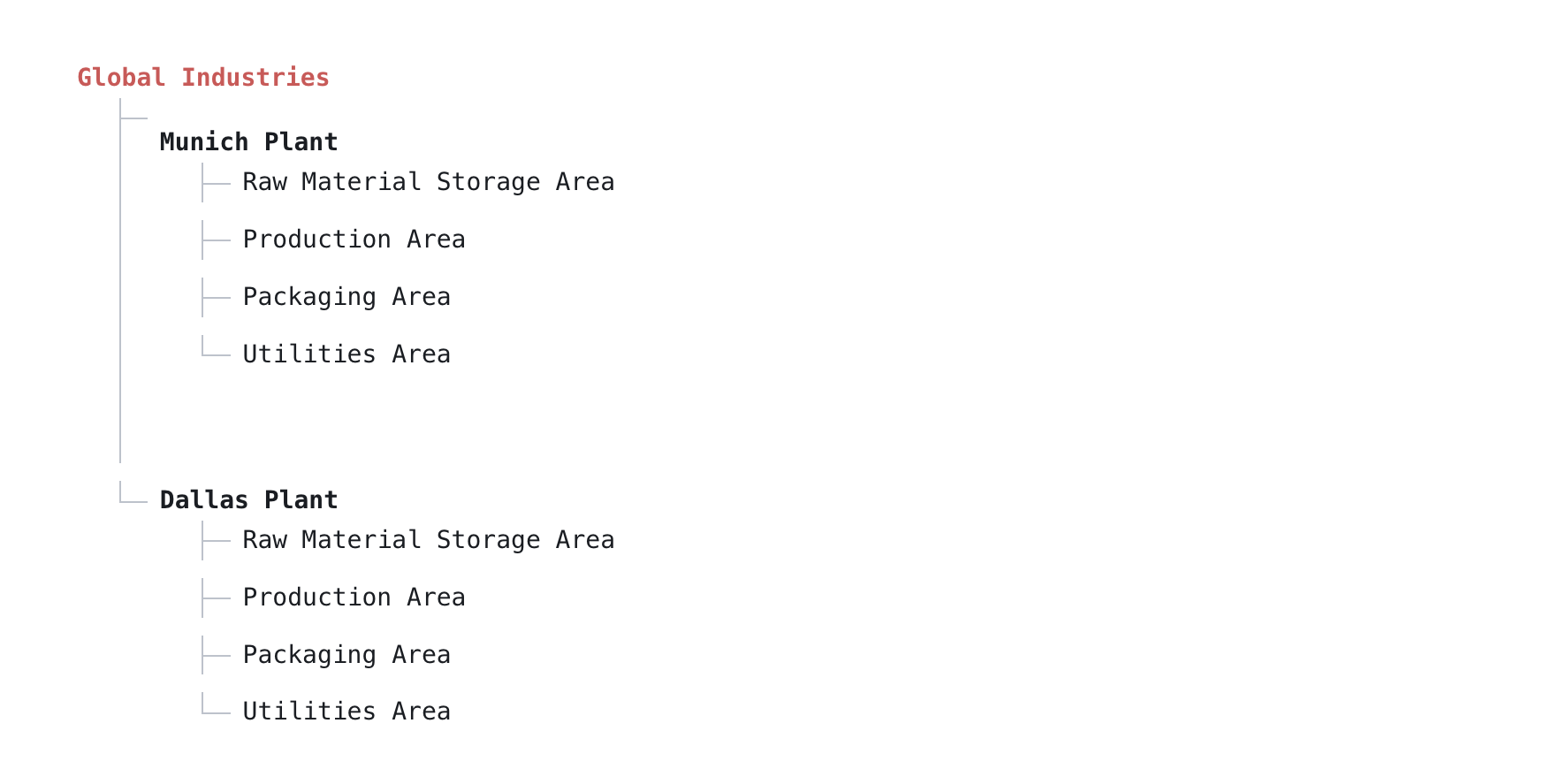
Global Industries manufactruing enterprise has two sites: Munich Plant and Dallas Plant. Each site contains four operational areas: Raw Material Storage Area, Production Area, Packaging Area, and Utilities Area. Within each area are one or more work centers that represent the more specific parts of the plant where operational activities take place.
The Class Layer and the Instance Layer
Our approach is to model the ontology and the Knowledge Graph as two connected layers within the same graph database: a class layer, which represents the ontology, and an instance layer, which represents the Knowledge Graph.
This distinction is fundamental. A class describes a category of things. For example, ProductionArea is an ontology class that defines what a production area means within the manufacturing domain.
An instance represents a particular thing that exists in operational reality. For example, MunichProductionArea is a specific area within the Munich plant.
The connection between the two is expressed as:
MunichProductionArea IS_INSTANCE_OF ProductionArea
This allows the graph to connect real operational entities to the semantic definitions provided by the ontology.
Below is a simple Neo4j Cypher example showing how to create an ontology class, create an operational instance, and establish the IS_INSTANCE_OF relationship between them.
Class Layer:
(prod_area:Class {
   name: "ProductionArea",
   uri: ".../production/ProductionArea"
})Instance Layer:
(muc_prod_area:Instance {
   id: "AREA-MUC-200",
   name: "Production Area",
})The two layers are connected through:
(muc_prod_area)-[:IS_INSTANCE_OF]->(prod_area)
This gives the graph two complementary kinds of information:
-
Instance layer: What actually exists? Class layer: What does that thing mean?
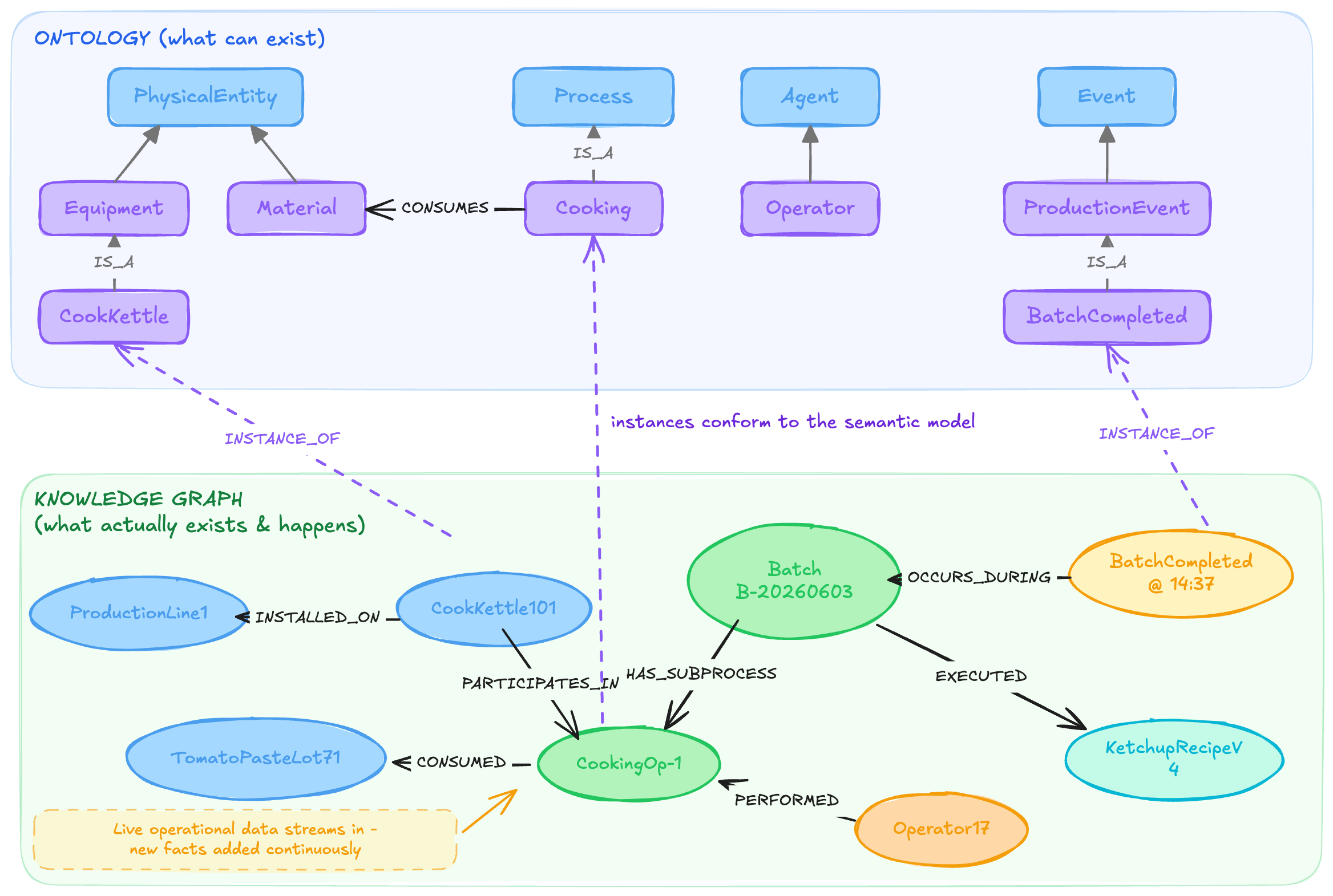
This is the convention we use throughout the framework, and up to this point our Neo4j graph has primarily described classes.
In the core manufacturing ontology, we defined Location as a class and then modeled the ISA-95 equipment hierarchy concepts Enterprise, Site, Area, and WorkCenter as subclasses of Location.
In the Production Operations domain ontology, we extended that hierarchy further by introducing more specific classes such as ProductionArea and PackagingArea beneath Area, and ProductionLine and PackagingLine beneath WorkCenter.
Until now, however, we have remained entirely within the class layer of the graph. We have described the kinds of locations that can exist, but not the actual locations that exist in our fictional manufacturing enterprise.
The next step is to build the instance layer by creating the real enterprise, sites, areas, and work centers that make up Global Industries, and then connecting each of those instances back to the appropriate ontology class.
Start with the Plant Topology
There is a practical reason to begin with the location hierarchy: it provides a relatively stable structure onto which the rest of the operational Knowledge Graph can be built.
Equipment can be located within work centers, processes can occur at specific locations, materials can be stored within inventory areas, and events can be associated with the part of the plant where they occurred. Establishing this topology first therefore gives later operational data a clear spatial context.
Other parts of the Knowledge Graph, such as equipment, process executions, material lots, events, and states, will be introduced later. Some, such as equipment definitions, can be added during engineering and commissioning, while more dynamic operational facts can be created continuously as data flows through the plant. In both cases, they will be integrated into the graph from the bottom up through a common data infrastructure.
Creating the Enterprise and Sites
Before creating the location instances, we first need to define a uniqueness constraint for their identifiers. Every operational instance in the Knowledge Graph is assigned a stable id, and that id must be unique. Two entities may share the same display name, but their unique identifiers ensure that they remain distinct operational entities.
CREATE CONSTRAINT instance_id IF NOT EXISTS
FOR (i:Instance)
REQUIRE i.id IS UNIQUE;
We can now create the top of the hierarchy.
The enterprise instance is created with:
MERGE (e:Instance:Location {id: 'GLOBAL-IND'})
ON CREATE SET e.created_at = datetime()
SET e:Enterprise,
    e.name = 'Global Industries',
    e.headquarters = 'Munich, DE',
    e.founded = date('2005-01-01');
Notice that the node carries several labels, :Instance, :Location, and :Enterprise
Each serves a different purpose.
:Instance distinguishes operational instances from ontology classes.
:Location allows applications to retrieve all location instances directly.
:Enterprise identifies the structural ISA-95 level of the location.
The Munich and Dallas sites follow the same pattern:
MERGE (muc:Instance:Location {id: 'SITE-MUC'})
ON CREATE SET muc.created_at = datetime()
SET muc:Site,
  muc.name = 'Munich Plant',
  muc.location = 'Munich, DE',
  muc.latitude = 48.1351,
  muc.longitude = 11.5820,
  muc.timezone = 'Europe/Berlin';
Properties such as geographic coordinates and time zone are facts about the individual site rather than part of the ontology itself. This is another useful distinction:
Ontology: What is a Site?

Knowledge Graph: Where is this site? What is it called? Which time zone does it operate in? When was it commissioned?
Creating Areas and Work Centers
Each site is divided into the ISA-95 Area level. For this example, both plants contain four areas:
100 — Raw Material Storage
200 — Production
300 — Packaging
400 — Utilities
For Munich:
MERGE (a:Instance:Location {id: 'AREA-MUC-200'})
ON CREATE SET a.created_at = datetime()
SET a:Area,
    a.name = 'Production Area',
    a.isa95_code = 200;
The work centers underneath those areas represent more specific operational locations.
For example:
MERGE (wc:Instance:Location {id: 'WC-MUC-200-L1'})
ON CREATE SET wc.created_at = datetime()
SET wc:WorkCenter,
    wc.name = 'Line 1',
    wc.description = 'Primary production line.';
and:
MERGE (wc:Instance:Location {id: 'WC-MUC-400-ST'})
ON CREATE SET wc.created_at = datetime()
  SET wc:WorkCenter,
      wc.name = 'Steam System',
      wc.description = 'Steam generation and distribution.';
There is an important modeling detail here. A node such as AREA-MUC-200 carries the structural label :Area, but its more specific semantic type is ProductionArea.
Rather than adding :ProductionArea as another Neo4j label, we connect the instance to the corresponding ontology class:
AREA-MUC-200 IS_INSTANCE_OF ProductionArea
This gives us two complementary ways to work with each location. For efficient operational queries, Neo4j can use the structural labels :Enterprise, :Site, :Area, and :WorkCenter. For semantic reasoning, the graph follows the IS_INSTANCE_OF relationship into the ontology to determine what the location actually represents within the manufacturing domain.
In other words, the instance layer remains simple and efficient to query, while still being semantically grounded in the ontology.
Now let’s look at how to connect location instances to their ontology classes using IS_INSTANCE_OF.
Connecting Instances to Their Ontology Classes
Now that the location instances exist, the next step is to connect each one to the ontology class that defines what kind of location it is. This is done using the IS_INSTANCE_OF relationship.
For the enterprise, we first match the Global Industries instance and the Enterprise class, then connect them:
MATCH
   (i:Instance:Location {id: 'GLOBAL-IND'}),
   (c:Class {name: 'Enterprise'})
MERGE (i)-[:IS_INSTANCE_OF]->(c);This creates the semantic statement: Global Industries IS_INSTANCE_OF Enterprise
The same pattern applies to the sites. Because all site IDs follow the convention SITE-..., we can match them as a group and connect them to the Site ontology class:
MATCH
   (i:Instance:Location),
   (c:Class {name: 'Site'})
WHERE i.id STARTS WITH 'SITE-'
MERGE (i)-[:IS_INSTANCE_OF]->(c);
This creates: Munich Plant IS_INSTANCE_OF Site and Dallas Plant IS_INSTANCE_OF Site
You will notice that, because we use a consistent naming convention for node IDs, it becomes straightforward to identify groups of entities using patterns such as STARTS WITH. In practice, you may not have the freedom to define new identifiers yourself, but most organizations already have established conventions for asset, location, or system IDs.
Connecting Areas
The area instances can now be connected to the more specific domain classes defined in the ontology. Rather than typing every area simply as Area, we use the area code embedded in the instance ID to determine what kind of area it represents.
In this example, the convention is:
100 = Warehouse
200 = ProductionArea
300 = PackagingArea
400 = UtilitiesArea
All raw-material storage areas use area code 100, so we connect them to the Warehouse class:
MATCH
   (i:Instance:Location),
   (c:Class {name: 'Warehouse'})
WHERE i.id STARTS WITH 'AREA-'
 AND split(i.id, '-')[2] = '100'
MERGE (i)-[:IS_INSTANCE_OF]->(c);
The same pattern is used for the production areas:
MATCH
    (i:Instance:Location),
    (c:Class {name: 'ProductionArea'})
WHERE i.id STARTS WITH 'AREA-'
  AND split(i.id, '-')[2] = '200'
MERGE (i)-[:IS_INSTANCE_OF]->(c);
This creates relationships such as:AREA-MUC-200 IS_INSTANCE_OF ProductionArea
AREA-DAL-200 IS_INSTANCE_OF ProductionArea
Packaging areas are connected to the PackagingArea class:
MATCH
    (i:Instance:Location),
    (c:Class {name: 'PackagingArea'})
WHERE i.id STARTS WITH 'AREA-'
  AND split(i.id, '-')[2] = '300'
MERGE (i)-[:IS_INSTANCE_OF]->(c);
And utility areas are connected to UtilitiesArea:
MATCH
    (i:Instance:Location),
    (c:Class {name: 'UtilitiesArea'})
WHERE i.id STARTS WITH 'AREA-'
  AND split(i.id, '-')[2] = '400'
MERGE (i)-[:IS_INSTANCE_OF]->(c);
Connecting Work Centers
The same approach can be applied at the WorkCenter level, although the classification becomes slightly more varied.
Storage work centers are connected to the StorageZone class:
// Storage work-centers -> StorageZone.
MATCH (i:Instance:Location), (c:Class {name: 'StorageZone'})
WHERE i.id STARTS WITH 'WC-' AND split(i.id, '-')[2] = '100'
MERGE (i)-[:IS_INSTANCE_OF]->(c);
Production-line work centers are connected to the ProductionLine class:
// Production lines -> ProductionLine (area 200, not the CIP station).
MATCH (i:Instance:Location), (c:Class {name: 'ProductionLine'})
WHERE i.id STARTS WITH 'WC-' AND split(i.id, '-')[2] = '200' AND split(i.id, '-')[3] STARTS WITH 'L'
MERGE (i)-[:IS_INSTANCE_OF]->(c);
The additional condition here excludes work centers such as the CIP station, which belongs to the production area but is not itself a production line.
Packaging-line work centers are connected to PackagingLine:
// Packaging lines -> PackagingLine (area 300).
MATCH (i:Instance:Location), (c:Class {name: 'PackagingLine'})
WHERE i.id STARTS WITH 'WC-' AND split(i.id, '-')[2] = '300'
MERGE (i)-[:IS_INSTANCE_OF]->(c);
So, at the semantic level:
Storage work center IS_INSTANCE_OF StorageZone
Production line IS_INSTANCE_OF ProductionLine
Packaging line IS_INSTANCE_OF PackagingLine
This is one of the advantages of building the ontology as an extensible hierarchy. The Knowledge Graph does not need to wait until every possible specialization has been modeled. An instance can initially be classified against a broader class and later be connected to a more specific class if that distinction becomes useful.
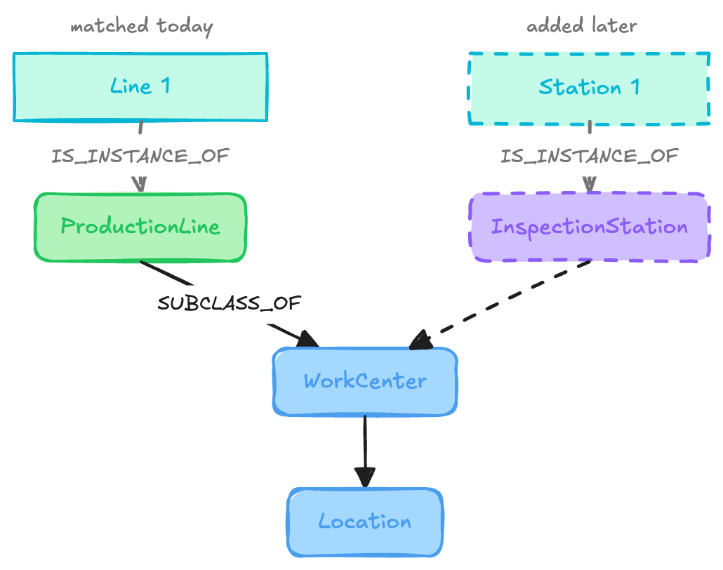
Importantly, the operational entity itself does not change. Its stable id remains the same; only its semantic classification becomes more precise as the ontology evolves.
Creating relationships between instances
Typing the location instances tells us what each location is, but a Knowledge Graph must also describe how those locations are connected.
In the core ontology, we already defined the CONTAINS relationship to represent structural containment between locations. We can now use that same relationship in the instance layer to describe the actual plant hierarchy.
In this framework, CONTAINS is directed from parent to child:
Enterprise CONTAINS Site
Site CONTAINS Area
Area CONTAINS WorkCenter
You could model the hierarchy in the opposite direction using a relationship such as IS_PART_OF, for example WorkCenter IS_PART_OF Area. Both approaches are valid. In this framework, however, we use CONTAINS consistently because it gives us a simple top-down way to traverse the enterprise structure.
At the instance level, the same pattern becomes:
Global Industries CONTAINS Munich Plant
Munich Plant CONTAINS Production Area
Production Area CONTAINS Line 1
Once the relevant instances exist, creating these relationships in Neo4j is straightforward.
Enterprise to site
We can first connect the enterprise to the sites it contains:
MATCH
   (e:Instance:Location {id: 'GLOBAL-IND'}),
   (s:Instance:Site)
MERGE (e)-[:CONTAINS]->(s);Because the query matches all nodes carrying the :Site structural label, it creates a CONTAINS relationship from Global Industries to both sites.
The resulting structure is:
Global Industries
├── Munich
└── Dallas
Site to area
We can then connect a site to the areas that belong within it. For example, to connect the Munich site to its production area:
MATCH (site:Instance:Location {id: 'SITE-MUC'})
MATCH (area:Instance:Location {id: 'AREA-MUC-200'})
MERGE (site)-[:CONTAINS]->(area);
This creates: Munich Plant CONTAINS Production Area. The same pattern can be repeated for the other areas within the site.
Area to work center
Finally, we connect each area to the work centers it contains. For example, the Munich production area contains its primary production line:
MATCH
    (a:Instance:Area {id: 'AREA-MUC-200'}),
    (wc:Instance:WorkCenter {id: 'WC-MUC-200-L1'})
MERGE (a)-[:CONTAINS]->(wc);
This creates:
Production Area CONTAINS Line 1
At this point, the location instances are no longer a collection of disconnected records. They form a traversable representation of the plant hierarchy:
Global Industries
    CONTAINS Munich Plant
        CONTAINS Production Area
            CONTAINS Line 1
Because the instance layer uses the same CONTAINS relationship defined in the ontology, the operational structure remains aligned with the semantic model. Applications and AI agents can now navigate the graph from the enterprise down to an individual work center and understand where that location sits within the wider manufacturing organization.
The Complete Class-to-Instance Pattern
With the location hierarchy connected and each instance linked to its ontology class, we can now follow a complete path from a real operational entity to its semantic meaning.
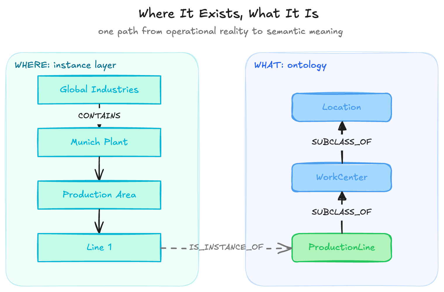
This path brings together the two layers of the graph.
The instance layer tells us where Line 1 exists in the operational structure of the enterprise. We can traverse from Global Industries, through the Munich Plant and its Production Area, down to the specific work center.
The class layer tells us what Line 1 means semantically. Through IS_INSTANCE_OF, we know that it is a ProductionLine. The ontology then tells us that a ProductionLine is a type of WorkCenter, which in turn is a type of Location.
This is the fundamental class-to-instance pattern we will use throughout the manufacturing Knowledge Graph. As we later add equipment, materials, processes, events, and states, each operational instance can be placed within the real structure of the plant while remaining connected to the semantic definitions provided by the ontology.
Querying Across the Instance and Class Layers
Once the instance and class layers are connected, the graph can be queried across both at the same time. This is where the model starts to become especially useful: a query can retrieve not only an operational entity, but also its semantic classification and its position within the wider plant structure.
Retrieve an Instance and Its Class
For example, we can retrieve WC-MUC-200-L1 and follow its IS_INSTANCE_OF relationship to the ontology:
MATCH
   (instance:Instance {id: 'WC-MUC-200-L1'})
   -[:IS_INSTANCE_OF]->
   (class:Class)
RETURN
   instance.id,
   instance.name,
   labels(instance),
   class.name,
   class.description;
Instance: WC-MUC-200-L1
Name: Line 1
Structural level: WorkCenter
Ontology class: ProductionLine
The name Line 1 on its own is ambiguous. It could refer to a production line, packaging line, or some other work center. By following IS_INSTANCE_OF, the graph tells us that this particular Line 1 is semantically a ProductionLine.
Retrieve All Production Lines
Because the semantic classification is explicit, we can also retrieve all production-line instances directly from the ontology class:
MATCH
   (line:Instance)
   -[:IS_INSTANCE_OF]->
   (:Class {name: 'ProductionLine'})
RETURN
   line.id,
line.name;This is more reliable than searching for names that happen to contain words such as production or line. The query is based on what the entities are, not how they happen to be named.
Retrieve the Plant Topology
We can also traverse the instance relationships themselves. For example, the following query starts at Global Industries and follows the CONTAINS hierarchy through the plant:
MATCH path =
   (enterprise:Instance {id: 'GLOBAL-IND'})
   -[:CONTAINS*]->
   (location:Instance)
RETURN path;
This gives us the full topology beneath the enterprise, from sites down through areas and work centers.
Retrieve the Context of a Work Center
Because the hierarchy is represented explicitly, we can also ask where a particular work center sits within the organization:
MATCH
   (site:Instance:Site)
   -[:CONTAINS]->
   (area:Instance:Area)
   -[:CONTAINS]->
   (workCenter:Instance {id: 'WC-MUC-200-L1'})
RETURN
   site.name AS site,
   area.name AS area,
workCenter.name AS workCenter;The result is:
Site: Munich Plant
Area: Production Area
Work center: Line 1
So the graph can answer both what the entity is and where it exists.
Query Through the Ontology Hierarchy
We can also use the ontology itself as part of the query. For example, the following query finds every instance whose class ultimately specializes Location:
MATCH
  (instance:Instance)
  -[:IS_INSTANCE_OF]->
  (class:Class)
  -[:SUBCLASS_OF*0..]->
  (:Class {name: 'Location'})
RETURN
  instance.id,
  instance.name,
class.name AS specificClass;This is a powerful pattern because the query does not need to know every possible location subclass in advance. If new classes such as MaintenanceWorkshop, InspectionStation, or MeteringPoint are added later beneath Location, they can still be discovered through the same ontology-driven query.
For applications, and especially AI agents, this is where the combination of ontology and Knowledge Graph becomes valuable. An agent can move from a specific operational entity to its plant context, semantic type, and broader class hierarchy without relying on brittle naming conventions or hard-coded database knowledge. The graph itself provides both the facts and the meaning needed to interpret them.
Conclusion
We have now moved from defining an ontology to using it to build the first instance layer of a manufacturing Knowledge Graph, connecting real plant locations to their semantic classes and to one another.
In the next article, I demonstrate how to extend the graph with equipment definitions and show how they can be attached to the Knowledge Graph through a common data infrastructure built around Industrial DataOps and the Unified Namespace.
Get the Next Guide
New architecture guides, implementation tutorials and use-case blueprints, delivered as they’re published.
More guides
All guides →

The leading IIoT & AI educational platform for digital manufacturing teams