
Connecting Industrial Assets to a Knowledge Graph Using MQTT, Node-RED, and Neo4j
We build a data pipeline that takes an MQTT message from a shop-floor system, transforms it into a Cypher write, and updates the knowledge graph in real time.

In the previous article, we moved from defining a manufacturing ontology to building the first instance layer of our Knowledge Graph. We created the structural hierarchy of Global Industries, its sites, areas, and work centers, and connected those operational instances back to the ontology classes that define what they mean.
That gave us the relatively stable plant topology onto which the rest of the operational Knowledge Graph can now be built.
The next step is to add the industrial assets that actually operate within that structure: fillers, conveyors, pumps, meters, compressors, and other equipment.
We could, of course, create these equipment instances manually in Neo4j. But that approach would quickly become impractical across hundreds or thousands of assets and, more importantly, would create another manually maintained representation of information that exists in a dynamic manufacturing environment.
Instead, we want equipment definitions to enter the Knowledge Graph, bottom-up, through the same data infrastructure that connects the rest of the plant.
In this article, we will use MQTT, Node-RED, and Neo4j to demonstrate that pattern. Equipment definitions will be published through the Unified Namespace, where Node-RED will act as an Industrial DataOps layer: consuming the messages, mapping the equipment to concepts defined in our ontology, and then creating or updating the corresponding knowledge graph in Neo4j.
Building the Equipment-to-Knowledge-Graph Pipeline
We already have an application publishing structured equipment-definition messages into the Unified Namespace over MQTT. We explore how those messages are created and how the topic hierarchy is designed in later articles. For now, our focus is on what happens when an equipment definition arrives and how we use it to extend the Knowledge Graph we have already created.
At this stage, the Knowledge Graph already knows that Global Industries has a Munich site, that the Munich site contains a Packaging Area, and that the packaging area contains a particular WorkCenter.
What it does not yet know is that a Krones rotary piston filler called FL-501 actually exists at that work center.
To bridge that gap, we will build a simple pipeline using MQTT, Node-RED, and Neo4j.
The pipeline we are going to build looks like this:
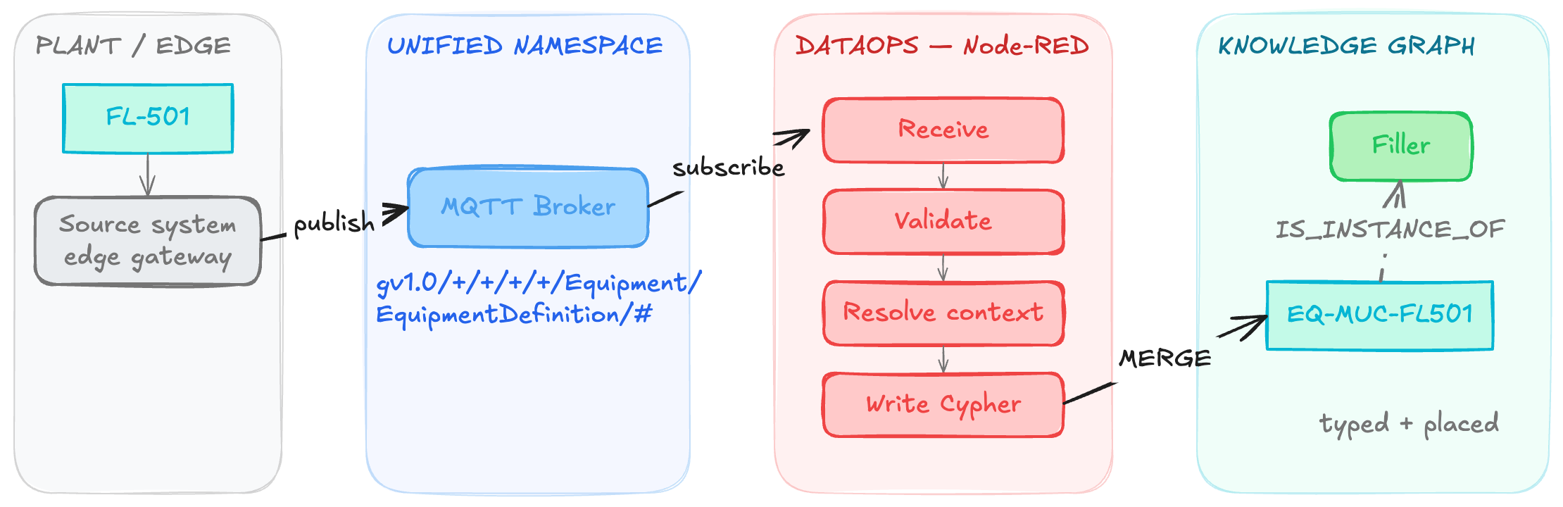
The Node-RED flow subscribes to:
gv1.0/+/+/+/+/Equipment/EquipmentDefinition/#
The wildcard subscription allows the same flow to receive equipment-definition messages published from different sites, areas, and work centers across the enterprise, provided they follow the common namespace structure.
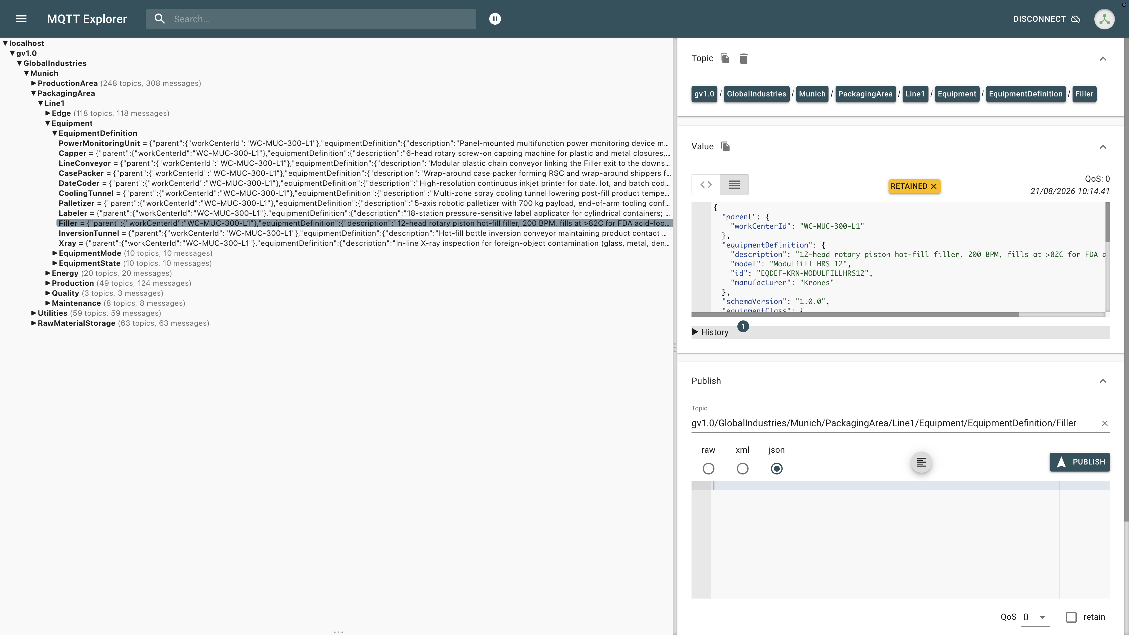
This is an important architectural pattern. Rather than creating a bespoke integration for each production line or equipment type, we establish a common event and data contract through which equipment can announce its definition.
Receiving Equipment Definition MQTT Payload
Consider the filler at the Munich packaging line.
When the equipment is initially onboarded, or when its master data changes, the source system publishes its complete definition:
{
  "schemaVersion": "1.0.0",
  "equipment": {
    "id": "EQ-MUC-FL501",
    "assetTag": "FL-501",
    "name": "Rotary Piston Filler FL-501",
    "lifecycleStatus": "commissioned",
    "serialNumber": "KRN-MF12-18-0912",
    "installationDate": "2018-11-05"
  },
  "equipmentClass": { "id": "EQCLASS-FILLER", "name": "Filler" },
  "equipmentDefinition": {
    "id": "EQDEF-KRN-MODULFILLHRS12",
    "manufacturer": "Krones",
    "model": "Modulfill HRS 12",
    "description": "12-head rotary piston hot-fill filler, 200 BPM, fills at >82C for FDA acid-food pasteurization"
  },
  "parent": { "workCenterId": "WC-MUC-300-L1" },
  "source": {
    "origin": "BatchPlantSimulator_OPCUA",
    "uri": "opc.tcp://localhost:26543/BatchPlantServer/Area500_Filling/Filler_FL501",
    "gateway": "Ignition-Gateway-001",
    "originSystemId": 1015
  },
  "quality": "Good",
  "timestamp": 1779277854779
}
The message contains several important pieces of context about the asset. The equipment section establishes the identity of the physical asset itself, while equipmentDefinition provides its make, model, and other definition-level details.
The equipmentClass identifies the broader source-system category the asset belongs to, the parent section identifies the work center where it is installed, and the source section preserves provenance by recording where the definition originated and which gateway or source system published it.
This gives the DataOps layer enough information to answer the two questions required to add the equipment to our Knowledge Graph:
What kind of thing is this? and Where does it exist?
Using Node-RED as the Mapping Layer
The MQTT message is consumed by a Node-RED flow.

The flow itself is relatively small because the objective is not to reproduce the ontology inside Node-RED. Node-RED performs four main jobs:
Receive → Validate → Resolve semantic context → Write to Neo4j
When the message arrives, the flow first verifies that the payload contains the required sections and stable identifiers. It then constructs a parameterized Cypher transaction for Neo4j.
This distinction is important. Node-RED does not become the semantic model. The ontology remains in Neo4j. Node-RED acts as the DataOps and mapping layer that connects incoming source-system data to that semantic model.
Creating the Equipment Instance
The first part of the Cypher transaction creates or updates the actual equipment instance:
MERGE (eq:Instance:Equipment {id: $eqId})
ON CREATE
SET eq.created_at = datetime()
SET eq.assetTag = $eqAssetTag,
	eq.name = $eqName,
    eq.equipmentType = $eqClassName,
    eq.lifecycleStatus = $eqLifecycleStatus,
    eq.serialNumber = $eqSerialNumber,
    eq.installationDate = date($eqInstallationDate),
    eq.manufacturer = $eqDefManufacturer,
    eq.model = $eqDefModel,
    eq.description = $eqDefDescription,
    eq.equipmentClassId = $eqClassId,
    eq.equipmentDefinitionId = $eqDefId,
    eq.sourceOrigin = $sourceOrigin,
    eq.sourceUri = $sourceUri,
    eq.sourceGateway = $sourceGateway,
    eq.sourceSystemId = $sourceSystemId,
    eq.schemaVersion = $schemaVersion,
    eq.lastSeenAt = datetime({epochMillis: $timestamp}),
    eq.lastSeenQuality = $quality
The stable equipment ID, EQ-MUC-FL501, becomes the identity used by the Knowledge Graph. And because we use MERGE, the same transaction can handle both the first equipment-definition message and subsequent updates.
If the asset does not yet exist, Neo4j creates it; If it already exists, its current definition is updated. This gives us:
EQ-MUC-FL501
    :Instance
    :Equipment

name = Rotary Piston Filler FL-501
manufacturer = Krones
model = Modulfill HRS 12
...
But at this point Neo4j only knows that it is an equipment instance. We still need to establish what kind of equipment it is.
Mapping the Asset to the Ontology
For a person looking at the payload, the semantic connection seems obvious, equipmentClass.name = "Filler", and our production ontology already contains Filler SUBCLASS_OF Equipment.
It would therefore be tempting simply to match the text "Filler" against the ontology class name.
However, the implementation deliberately avoids depending on display names. Names can be edited, translated, reformatted, or changed by a source application. Stable identifiers make a safer integration contract.
The Node-RED flow therefore resolves the ontology class in two stages. First, it checks whether the more specific equipmentDefinition.id has been bound to an ontology class.
For our filler, EQDEF-KRN-MODULFILLHRS12 may resolve directly to the appropriate equipment type. Where no definition-level mapping exists, the flow falls back to equipmentClass.id such as EQCLASS-FILLER
The basic resolution logic is therefore:
equipmentDefinition.id → specific ontology class → if unavailable → equipmentClass.id → ontology class
This is useful because a generic source-system class may not always provide enough semantic precision.
For example, a source system might classify several different vessels simply as Tank. The equipment definition, representing the actual make, model, or engineering definition, may provide enough information to distinguish a BufferTank from another type of storage or process vessel.
The mapping itself is maintained as ontology data rather than hidden inside the Node-RED flow. Once the appropriate class has been resolved, the graph creates:
EQ-MUC-FL501
    IS_INSTANCE_OF
Filler
The ontology can then tell us:
EQ-MUC-FL501
    IS_INSTANCE_OF Filler
        SUBCLASS_OF Equipment
            SUBCLASS_OF PhysicalEntity
The source message has now been connected to semantic meaning.
// Tier 2 — resolve using the more specific equipment definition
OPTIONAL MATCH (dcls:Class)
WHERE $eqDefId IS NOT NULL
  AND dcls.sourceDefinitionIds IS NOT NULL
  AND $eqDefId IN dcls.sourceDefinitionIds
  AND EXISTS {
      (dcls)-[:SUBCLASS_OF*]->(:Class {name: 'Equipment'})
  }

WITH eq, dcls

// Tier 1 — fall back to the equipment class
OPTIONAL MATCH (ccls:Class {sourceClassId: $eqClassId})
WHERE EXISTS {
    (ccls)-[:SUBCLASS_OF*]->(:Class {name: 'Equipment'})
}

WITH eq, coalesce(dcls, ccls) AS cls

// Connect the equipment instance to the resolved ontology class
FOREACH (c IN CASE WHEN cls IS NULL THEN [] ELSE [cls] END |
    MERGE (eq)-[:IS_INSTANCE_OF]->(c)
)
The flow first tries to resolve the more specific equipmentDefinition.id; if no mapping exists, it falls back to equipmentClass.id. In both cases, the resolved class must sit beneath Equipment in the ontology before the IS_INSTANCE_OF relationship is created.
Placing the Asset in the Existing Plant Topology
Knowing what the asset is is only half of the problem; we also need to know where it exists.
The equipment-definition payload contains:
"parent": {
 "workCenterId": "WC-MUC-300-L1"
}
That identifier points to the work-center instance we already created in the previous article. Node-RED uses it to resolve the location:
OPTIONAL MATCH
    (wc:Instance:WorkCenter {id: $parentWorkCenterId})
and then creates:
MERGE (eq)-[:IS_LOCATED_AT]->(wc)
The result is:
EQ-MUC-FL501
    IS_LOCATED_AT
WC-MUC-300-L1
The choice of relationship matters. We used CONTAINS when constructing the location hierarchy:
Site CONTAINS Area
Area CONTAINS WorkCenter
But equipment is not another location level; it is a PhysicalEntity. And our ontology already defines the appropriate relationship.
PhysicalEntity IS_LOCATED_AT Location
So the equipment is located at the work center rather than added as another level of the CONTAINS hierarchy.
This is exactly why having a core ontology first is useful: it gives the ingestion pipeline a consistent relationship vocabulary instead of letting each integration invent its own representation.
The Result in Neo4j
Once the transaction completes, the previously empty work center is now connected to an actual industrial asset. The resulting pattern looks roughly like:
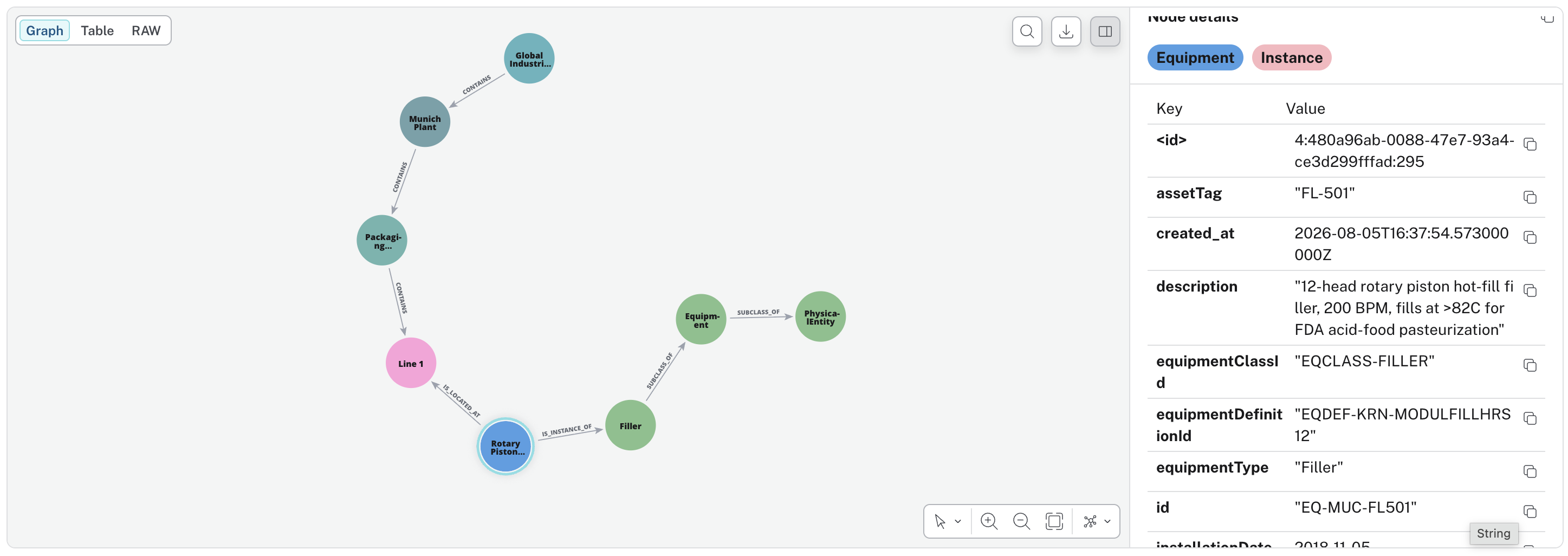
This is where the class and instance layers come together again. The plant topology tells us where the equipment exists, and the ontology tells us what the equipment is.
The equipment-definition message supplies the real operational entity that joins those two sides.
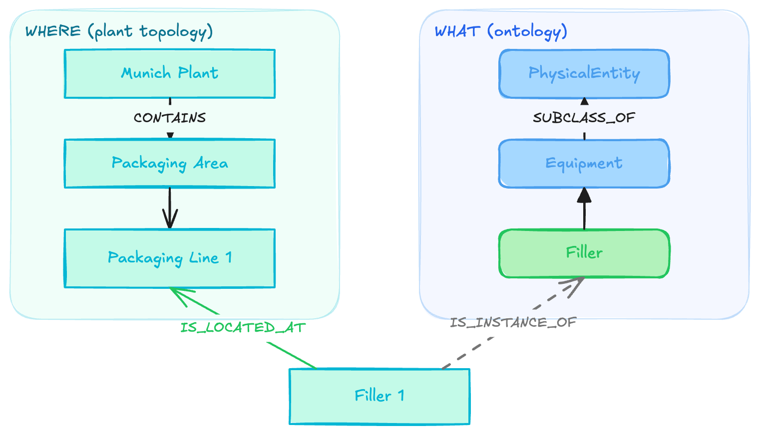
An AI agent traversing the graph can therefore discover that EQ-MUC-FL501 is a Filler, that a Filler is a type of Equipment, and that this particular filler is located on Packaging Line 1 at the Munich plant.
What Happens When the Definition Changes?
This pipeline is not intended only for first-time commissioning. The same equipment definition can be published whenever relevant master data changes.
Because the equipment instance is matched using its stable ID:
MERGE (eq:Instance:Equipment {id: $eqId})
a subsequent message updates the existing node rather than creating a duplicate.
Properties such as manufacturer, model, serialNumber, lifecycleStatus, sourceGateway, and equipmentDefinitionId can therefore remain synchronized with the source.
Semantic classification can also change. If the ontology binding for an asset changes, the current flow treats the equipment type as authoritative: an obsolete IS_INSTANCE_OF relationship to another equipment class can be removed and replaced with the newly resolved class.
That allows both the operational model and the semantic model to evolve without changing the stable identity of the asset.
For equipment movement between work centers, I would apply the same authoritative principle to IS_LOCATED_AT: replace the previous location relationship when parent.workCenterId changes rather than leaving multiple current locations attached to the asset.
Don't Silently Lose Context
Another important part of the pipeline is how it handles missing context. What happens if the incoming equipment class cannot be mapped to an ontology class? Or if WC-MUC-300-L1 does not yet exist in the plant topology?
The flow deliberately uses optional lookups and reports the outcome. This means an equipment instance can still be captured even when it cannot yet be completely contextualized, while the integration surfaces warnings such as Asset is untyped or Asset is unplaced.
That is preferable to silently dropping the message.
In a production implementation, these warnings can become data-quality signals. They tell us where the operational data and semantic model have drifted apart, for example, because a new equipment class has appeared before its ontology mapping has been governed.
This is an important role for Industrial DataOps: not simply transporting data, but continuously checking whether that data has enough context to be trusted and used downstream.
Building the Knowledge Graph from the Bottom Up
The bigger idea behind this example is not the specific filler, Cypher query, or Node-RED flow. It is the method. We began by deliberately constructing the relatively stable parts of the Knowledge Graph from the top down:
Ontology → Enterprise → Site → Area → WorkCenter
At that stage, the graph described the structure of the manufacturing environment but did not necessarily know every asset that existed within it. Equipment definitions now begin flowing upward from the operational environment:
Physical equipment → Source system / edge → Unified Namespace → Industrial DataOps → Ontology mapping → Knowledge Graph
Each definition adds another piece of operational reality.
The graph progressively moves from:
We know this packaging line exists to We know which filler exists on it.
And eventually to:
We know which processes the filler participates in, which materials pass through it, which events it generates, what state it is currently in, and how all of those facts relate to the rest of the plant.
Assuming the edge publishes equipment definitions on report by exception, this also becomes naturally event-driven. A definition is sent when an asset first appears or when relevant master data changes, rather than continuously retransmitting unchanged information.
The Knowledge Graph is therefore incrementally synchronized with the operational environment.
Conclusion
We have now shown how equipment definitions can move from the plant, through MQTT and an Industrial DataOps layer, into Neo4j where they become semantically typed and spatially contextualized instances in the manufacturing Knowledge Graph.
In the next article, we take a step back and look more closely at the Unified Namespace itself: what it is, how it fits into this architecture, and why it provides such a useful foundation for distributing operational context. From there, we will explore practical best practices for designing both the topic namespace and the payload structures that make this kind of semantic integration possible at scale.
Get the Next Guide
New architecture guides, implementation tutorials and use-case blueprints, delivered as they’re published.
More guides
All guides →

The leading IIoT & AI educational platform for digital manufacturing teams