
How to Design an Ontology for Manufacturing Operations
How do you actually design a manufacturing ontology? The first, and most important, decision is whether to take a top-down or bottom-up approach.

In a previous article, I explained that an ontology is a formal, machine-readable model of the entities that exist within a manufacturing domain, how those entities relate to one another, and the rules that govern them.
And that, one of its most valuable applications is in AI: when an ontology is made available to AI agents, it provides a structured representation of operational reality, helping probabilistic AI systems reason and act within clearly defined boundaries and constraints.
But how do you actually go about designing an ontology, particularly for manufacturing operations management?
One of the first, and most important, decisions is whether to take a top-down or bottom-up approach.
Choosing an Ontology-Building Approach
There are two common approaches to building an ontology: top-down and bottom-up.
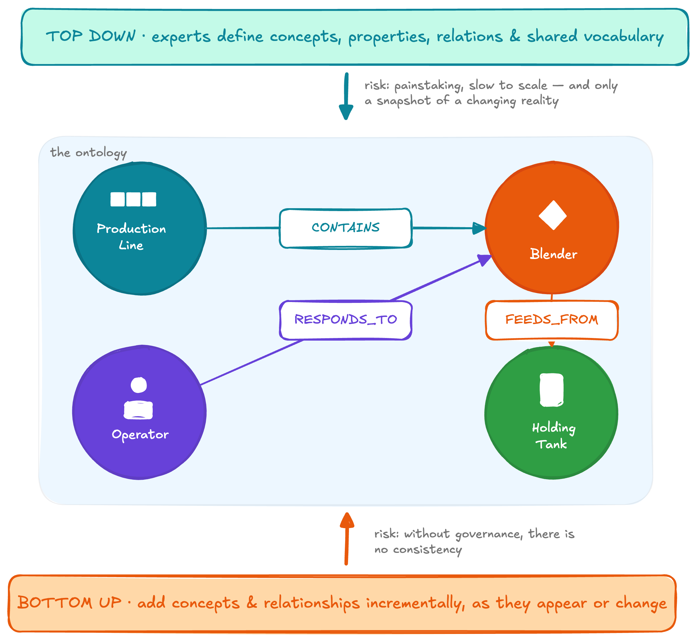
In a top-down approach, domain experts and other relevant stakeholders work together to model the domain. They identify the important concepts, define their properties, describe the relationships between them, and establish a shared vocabulary.
In theory, this allows you to create a comprehensive model of your manufacturing operations before implementing it.
In practice, however, trying to understand and formalize the entire language of manufacturing operations upfront is painstaking, time-consuming, and difficult to scale. No single person or team fully understands the operational reality across every plant, production process, and business domain.
Even if you successfully captured that reality, you would only be representing the organization as it exists at that moment. Equipment, processes, responsibilities, and operational practices will continue to change.
The alternative is a bottom-up approach.
Here, you add concepts, properties, and relationships incrementally as they appear, change, or become relevant.
For example, when a new machine or capability is added to a production line, you add it to the model. When you discover that, despite what the plant diagram shows, a blender actually feeds from Holding Tank 1 rather than Holding Tank 2, you update that relationship. When you learn which conditions operators actually respond to during production, you capture that operational knowledge as well.
This approach is more adaptable and better reflects the reality of a changing manufacturing environment.
However, it introduces another risk. Without shared rules and governance, different teams may describe the same concepts in different ways. One site may define a machine as an Asset, another as Equipment, and another as a Work Unit. Over time, the ontology can become an inconsistent collection of locally defined concepts that is no longer useful across the organization.
The most practical solution is therefore a hybrid approach.
You begin by defining a small core ontology containing a limited set of stable, highly abstract concepts and relationships. Individual operational domains can then extend that foundation from the bottom up as new requirements, assets, processes, and relationships emerge.
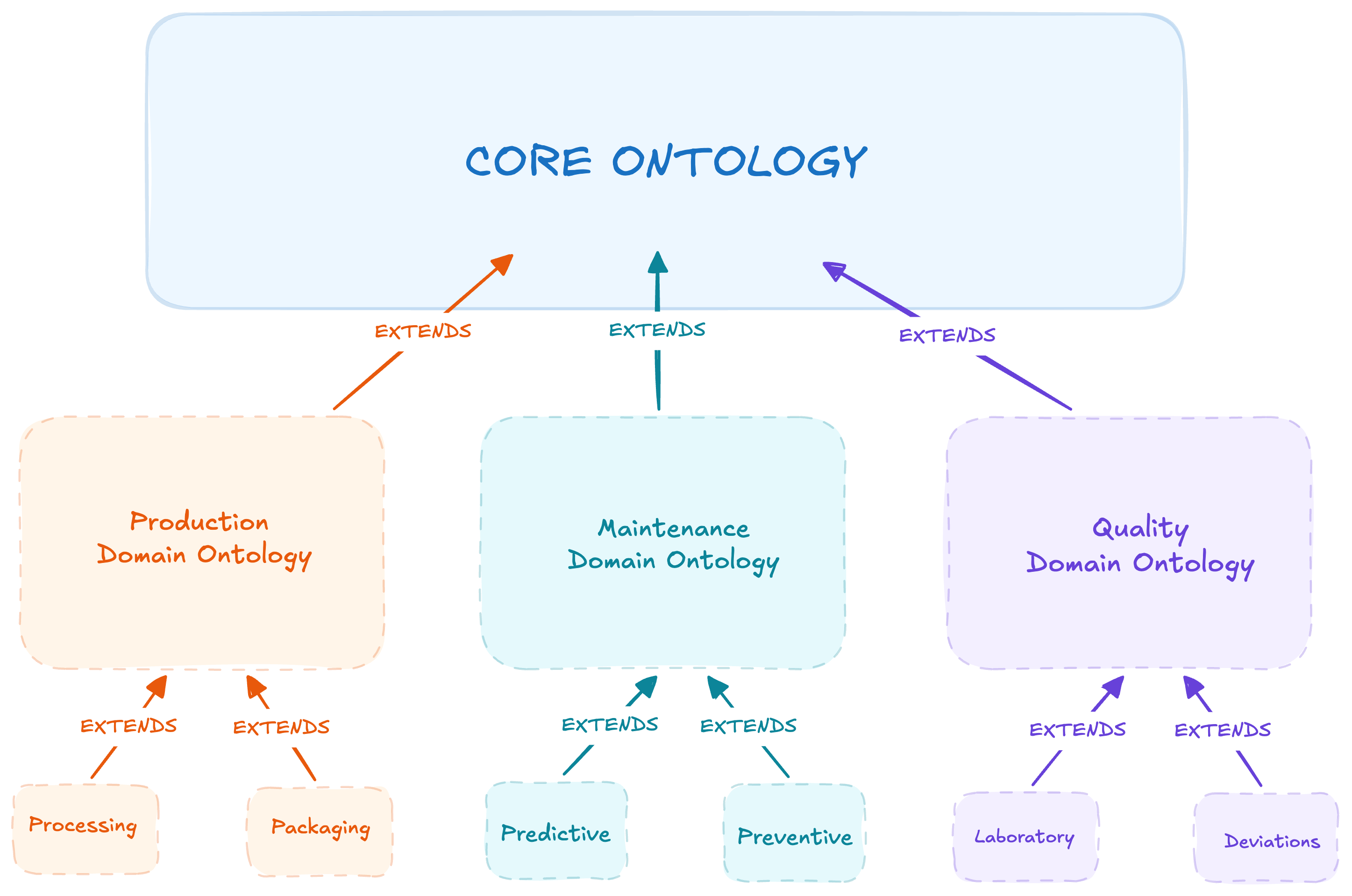
This gives teams the flexibility to model their operational reality without losing consistency across the organization.
Defining The Core Concepts of a Manufacturing Operations Ontology
The first step is to define the core ontology. The key requirement is that it remains small and precise enough to constrain interpretation, while also being extensible enough to support different manufacturing domains without forcing them into one oversized universal schema.
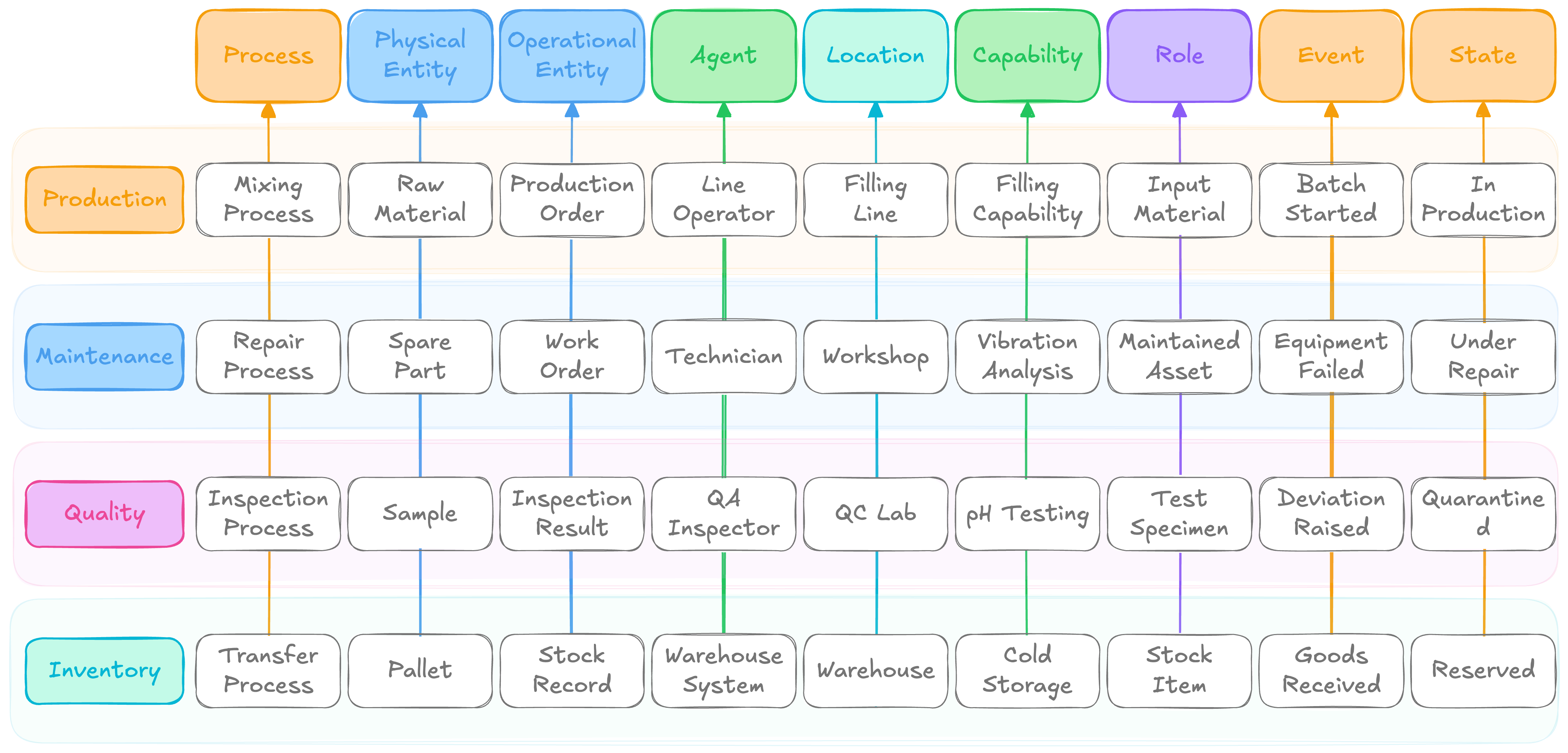
At a high level, most manufacturing operations can be described using a relatively small set of fundamental concepts. Based on this, I would structure the core manufacturing ontology around nine concepts: Process, PhysicalEntity, OperationalEntity, Location, Capability, Role, Agent, Event, and State.
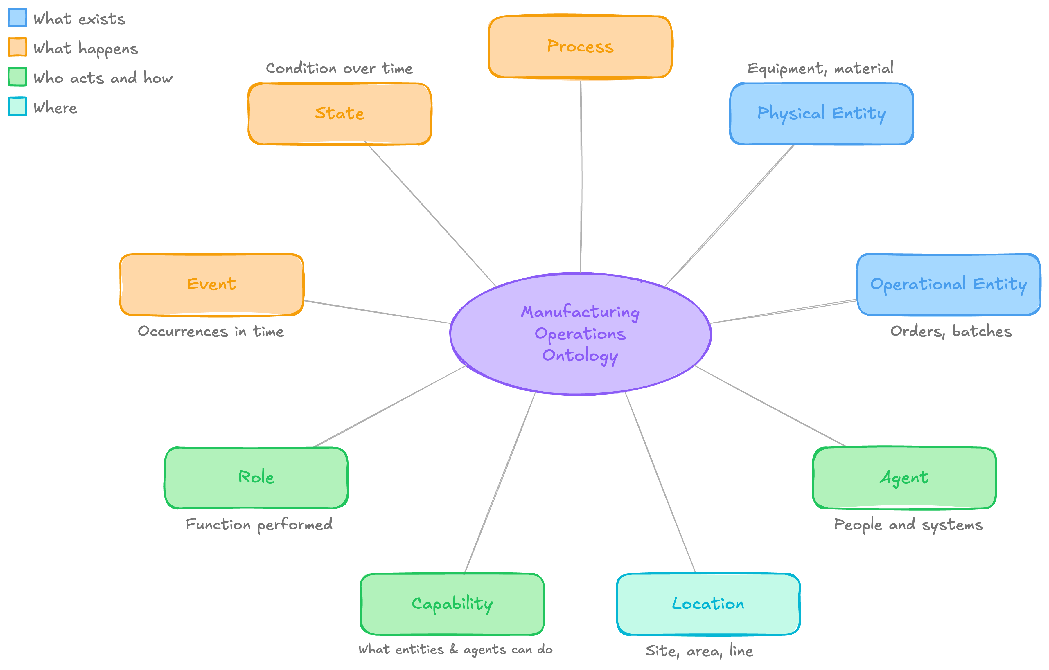
Let us examine each of these concepts in more detail.
Core Concept 1: Process
A Process represents work that happens over time and creates, transforms, moves, inspects, maintains, or otherwise affects something. For example, Mixing, Welding, Packaging, Inspection, Cleaning, and Material transfer.
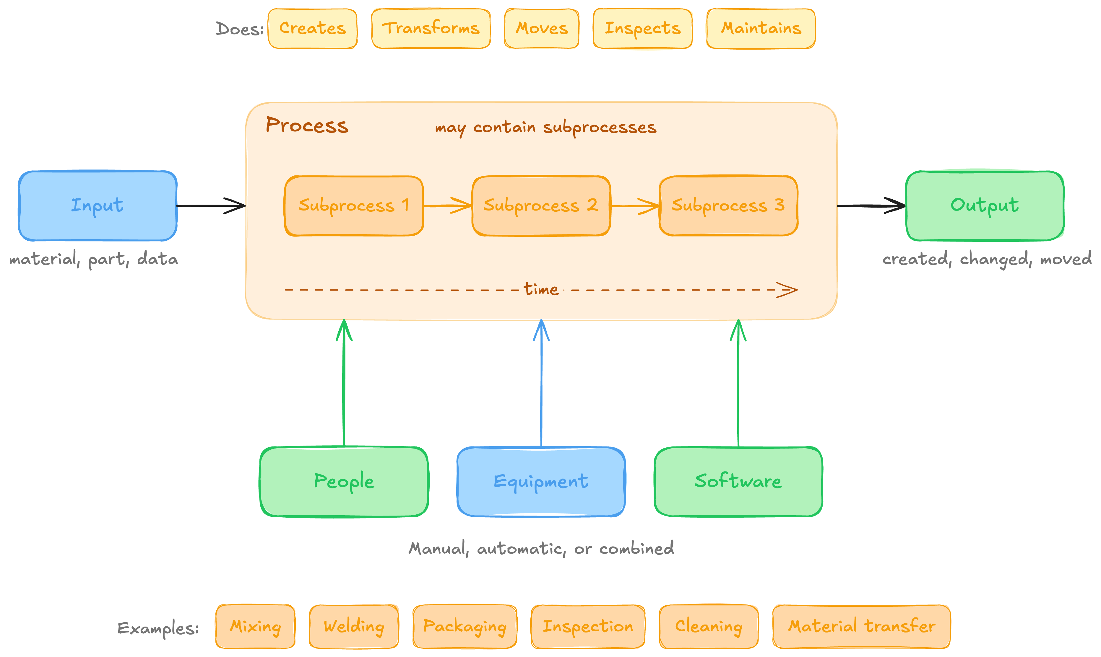
A process may contain subprocesses and may be executed manually, automatically, or through a combination of people, equipment, and software.
Core Concept 2: PhysicalEntity
A PhysicalEntity is a physical entity that exists within the manufacturing environment. For example, Material, Product, Equipment, Tool, Container, and Sample.
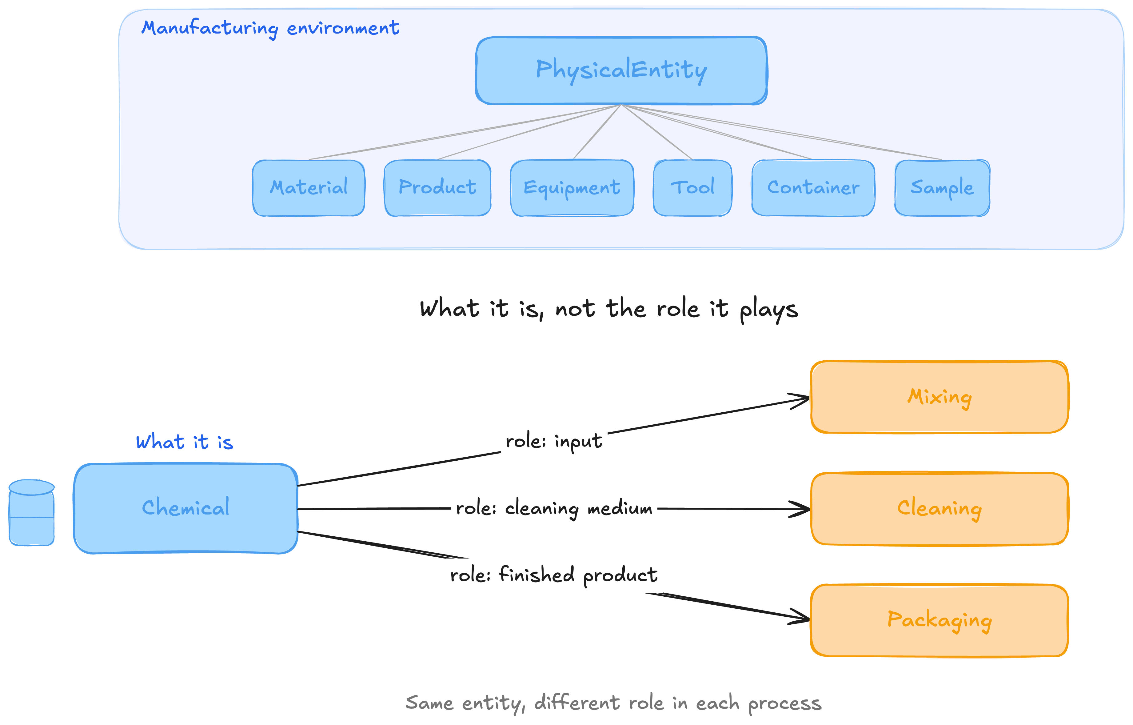
The concept describes what something is, not the role it plays in a particular process.
3. OperationalEntity
An OperationalEntity is an informational object that directs, constrains, describes, or records operational work.For example, Order, Schedule, Recipe, Procedure, Specification, Work instruction, Production record, Inspection result.
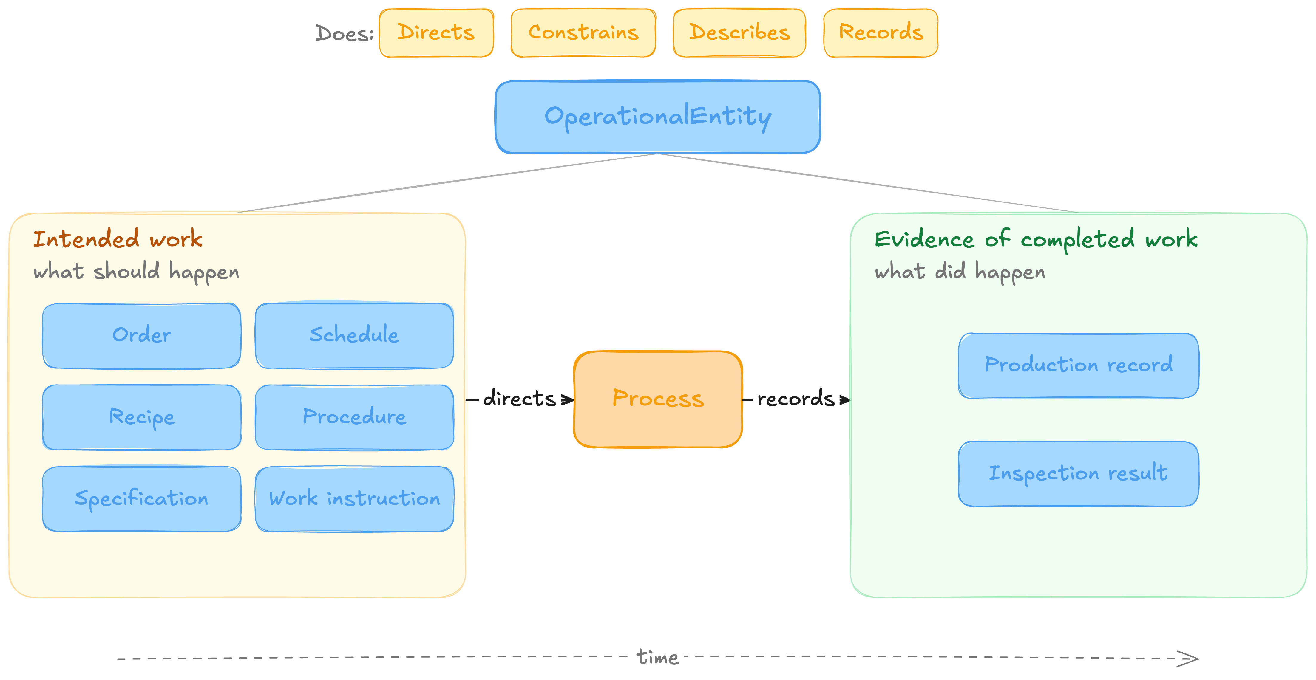
Operational entities can be divided broadly into those that describe intended work and those that provide evidence of completed work.
4. Agent
An Agent is something capable of participating in, controlling, or making decisions about a process. For example, Personnel, Team, Equipment controller, Software application, and AI agent.
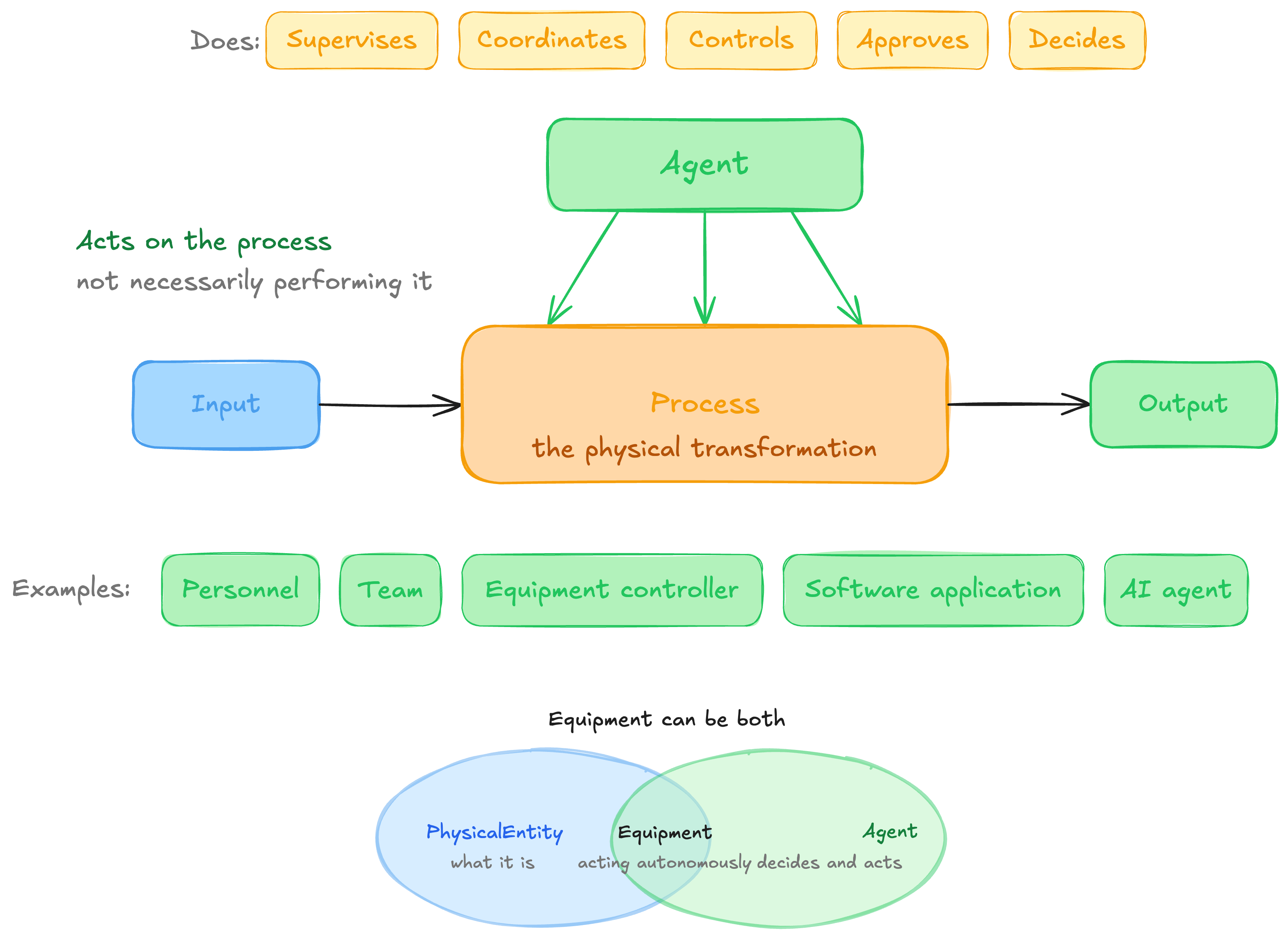
An agent does not necessarily perform the physical transformation itself. It may supervise, coordinate, control, approve, or make decisions about the process.
Equipment can be both a PhysicalEntity and, where it acts autonomously, a type of Agent.
5. Location
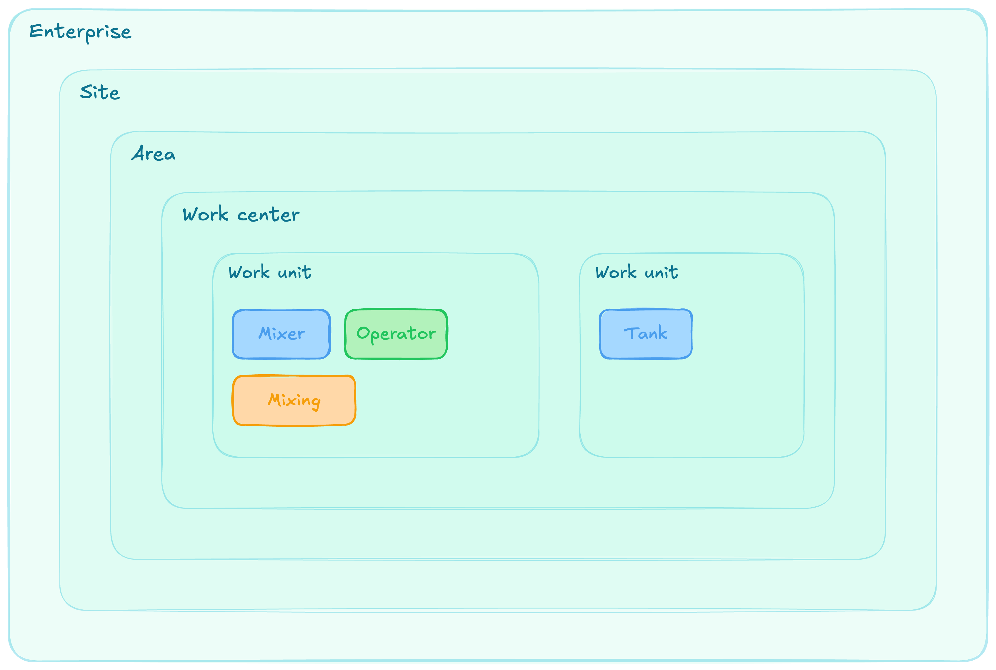
A Location represents where an entity, agent, or process exists or occurs. For example, Enterprise, Site, Area, Work center and Work unit. The ISA-95 equipment hierarchy model would extend this concept.
6. Capability
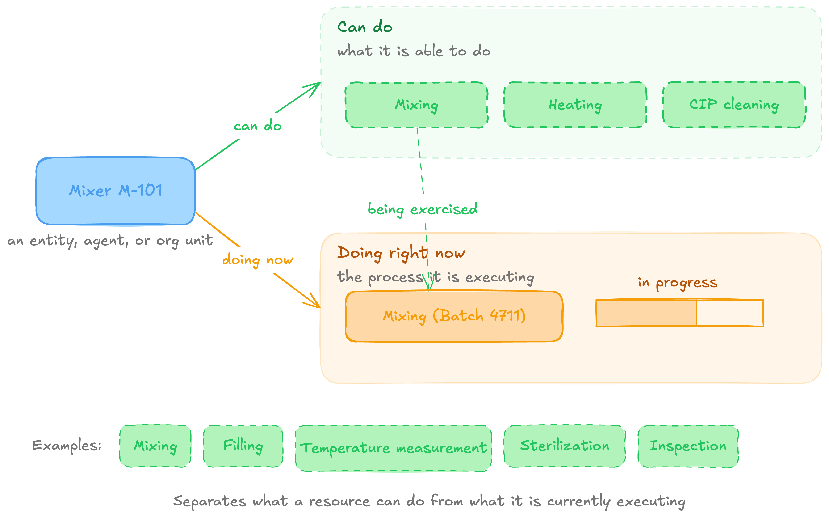
A Capability describes what an entity, agent, or organizational unit is able to do. For example, Mixing capability, Filling capability, Temperature-measurement capability, Sterilization capability, Inspection capability. This separates what a resource can do from the process it is currently executing.
7. Role
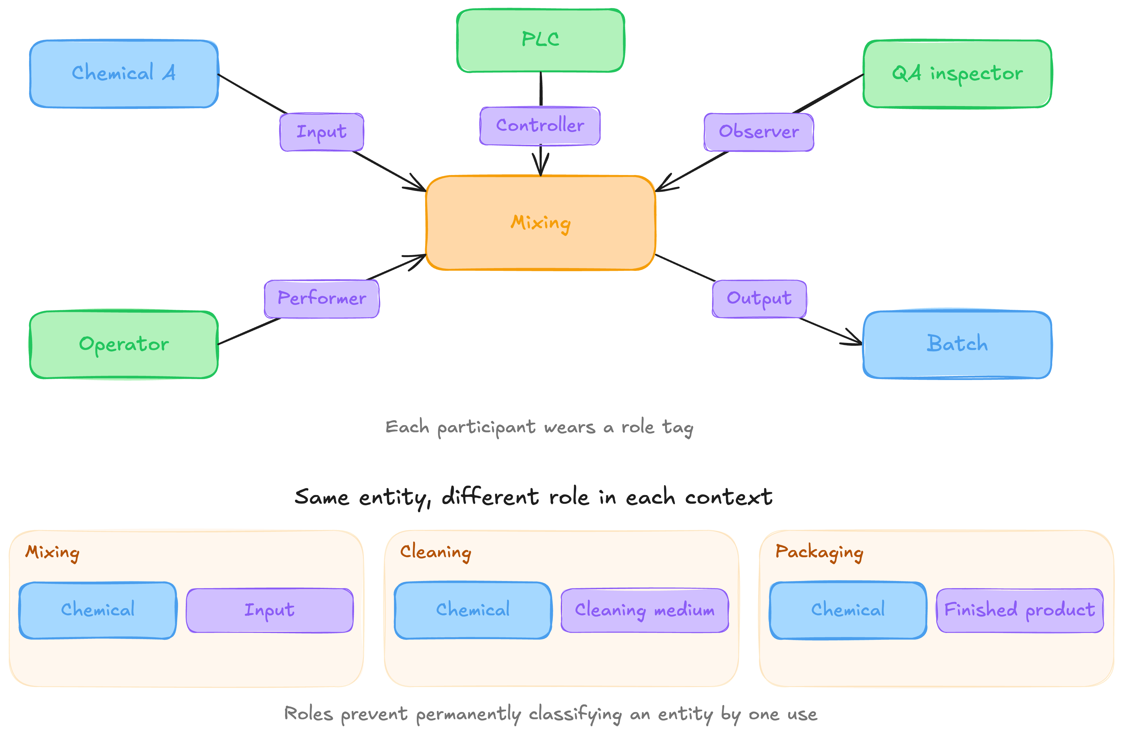
A Role describes how an entity participates in a particular process or relationship. For example, Input, Output, Performer, Observer, Controller, Consumer, and Producer.
This is important because the same entity may play different roles in different contexts.
For example, a chemical may be an input material in one process, a cleaning medium in another, and a finished product in another. Modelling roles prevents us from permanently classifying it according to only one use.
8. Event
An Event represents something operationally significant that occurred at a particular point or interval in time. For example, Process started, Order released, Material consumed, Alarm activated, Inspection completed and Equipment failed.
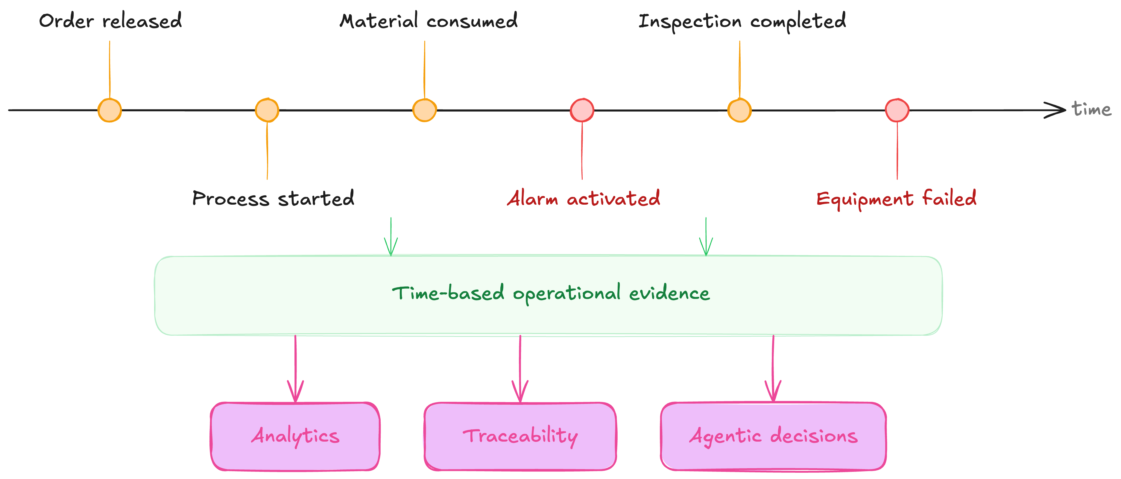
Events provide the time-based operational evidence needed for analytics, traceability, and agentic decision-making.
9. State
A State describes the condition of an entity or process during a period of time. For example, Running, Idle, Failed, Available, In production, Awaiting inspection, Released, Quarantined
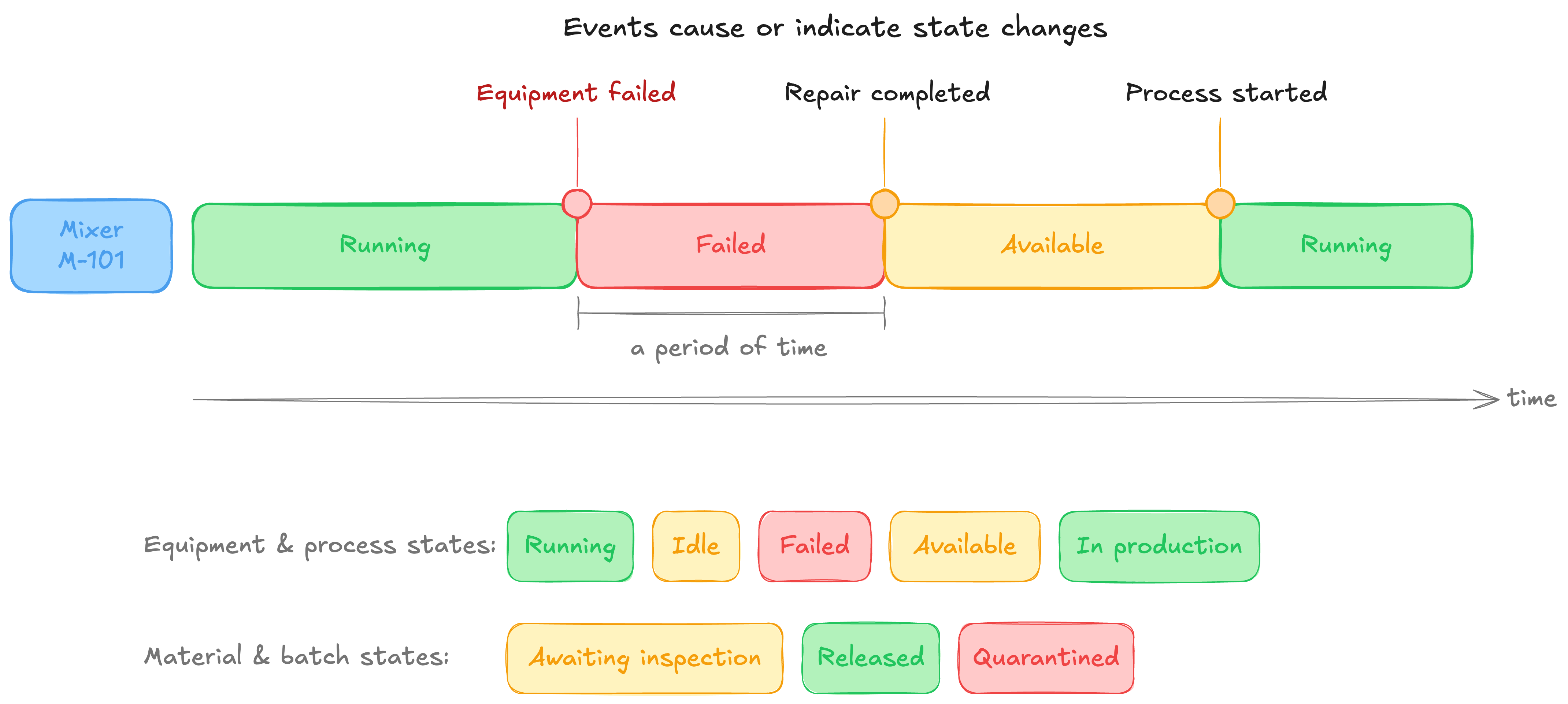
Events usually cause or indicate state changes:
EquipmentFailureEvent CHANGES_STATE Equipment
Equipment STATE Failed
The core consists of concepts that are abstract enough to describe manufacturing-wide semantics, but concrete enough to support useful operational models. More importantly, it does not attempt to define every machine type, failure mode, material property, inspection method, process parameter, or regulatory rule. Those belong in extensions, as shown in the diagrma below.
Defining The Core Relationships of a Manufacturing Operations Ontology
Once we have defined the core concepts, the next step is to define the relationships between them. Concepts tell us what kinds of things exist in the manufacturing operations domain. Relationships tell us how those things are connected.
This is important because an ontology is not simply a list of manufacturing terms. Its value comes from expressing the meaning of the connections between processes, physical entities, operational entities, agents, locations, capabilities, roles, events, and states.
The requirement here is similar to the requirement for the core concepts. The relationships should be general enough to work across production, maintenance, quality, inventory, and other manufacturing domains, but precise enough to constrain how those domains represent operational reality.
Based on the nine core concepts, I would define the core ontology around the following relationships.
1. Process AFFECTS PhysicalEntity
The AFFECTS relationship describes a physical entity that is changed, handled, moved, inspected, maintained, or otherwise influenced by a process. For example:
MixingProcess AFFECTS Material
InspectionProcess AFFECTS Product
MaintenanceProcess AFFECTS Equipment
CleaningProcess AFFECTS Container
This is the broadest relationship between a process and a physical entity. More specific relationships such as TRANSFORMS, MOVES, INSPECTS, CONSUMES, or PRODUCES can be introduced through domain extensions. These more specific relationships can be defined as specializations of AFFECTS.
2. Entity PARTICIPATES_IN Process
The PARTICIPATES_IN relationship identifies an entity that is involved in the execution of a process. For example:
Mixer PARTICIPATES_IN MixingExecution
Operator PARTICIPATES_IN MixingExecution
MaterialLot PARTICIPATES_IN MixingExecution
QualityApplication PARTICIPATES_IN InspectionExecution
Participation alone does not explain how the entity is involved. It simply establishes that the entity is part of the process context.
3. Entity PLAYS_ROLE Role
The PLAYS_ROLE relationship describes how an entity participates in a particular process, event, or operational context. For example:
MaterialLotA PLAYS_ROLE Input
MaterialLotB PLAYS_ROLE Output
Mixer101 PLAYS_ROLE Performer
Operator17 PLAYS_ROLE Supervisor
The relationship must be interpreted within a particular context. An entity does not necessarily play the same role permanently. For example, a chemical may play the role of an input material during a mixing process, a cleaning medium during a cleaning process, and an output during a purification process.
A more complete model would therefore associate the role with both the entity and the process:
MaterialLotA PLAYS_ROLE Input
Input ROLE_IN MixingExecution4711
4. Entity HAS_CAPABILITY Capability
The HAS_CAPABILITY relationship describes what an entity is able to do. For example:
Mixer HAS_CAPABILITY MixingCapability
Filler HAS_CAPABILITY FillingCapability
Sensor HAS_CAPABILITY TemperatureMeasurementCapability
Operator HAS_CAPABILITY ReactorOperationCapability
InspectionApplication HAS_CAPABILITY DefectDetectionCapability
This separates the potential ability of an entity from the work it is currently performing. A mixer may have a mixing capability even when it is idle. Similarly, a person may be qualified to perform an inspection without currently participating in an inspection process.
Capabilities may also include constraints or parameters. For example:
MixingCapability
    maximumVolume 2000 litres
    minimumSpeed 20 rpm
    maximumSpeed 250 rpm
Domain extensions may introduce more detailed concepts such as EquipmentCapability, PersonnelCapability, SoftwareCapability, or OrganizationalCapability.
5. Process REQUIRES_CAPABILITY Capability
The REQUIRES_CAPABILITY relationship describes the capability that must be available for a process to be executed. For example:
MixingProcess REQUIRES_CAPABILITY MixingCapability
SterilizationProcess REQUIRES_CAPABILITY SterilizationCapability
InspectionProcess REQUIRES_CAPABILITY VisualInspectionCapability
MaterialTransferProcess REQUIRES_CAPABILITY PumpingCapability
This allows the ontology to distinguish between the definition of the required work and the specific resource selected to perform it. For example:
MixingProcess REQUIRES_CAPABILITY MixingCapability
Mixer HAS_CAPABILITY MixingCapability
From these relationships, an application or AI agent can determine that Mixer101 may be a suitable participant in the mixing process.
However, possessing the required capability does not automatically mean that the resource should be selected. Other factors such as availability, current state, capacity, location, authorization, maintenance status, and scheduling constraints may also need to be evaluated.
6. Process IS_GUIDED_BY OperationalEntity
The IS_GUIDED_BY relationship connects a process to an operational entity that defines, directs, constrains, or governs how the process should be performed. For example:
MixingExecution IS_GUIDED_BY Recipe
InspectionExecution IS_GUIDED_BY QualitySpecification
CleaningExecution IS_GUIDED_BY CleaningProcedure
MaintenanceExecution IS_GUIDED_BY WorkInstruction
Different kinds of operational entities may guide a process in different ways. A recipe may define the sequence and parameters of a production process. A procedure may define the steps that personnel must follow. A specification may define acceptable limits. An order may authorize or request the work.
Domain extensions can therefore introduce more specific relationships such as:
Process EXECUTES Recipe
Process CONFORMS_TO Specification
Process FULFILLS Order
Process FOLLOWS Procedure
Process IS_SCHEDULED_BY Schedule
These relationships can be modeled as more precise specializations of IS_GUIDED_BY.
7. Process PRODUCES OperationalEntity
The PRODUCES relationship describes an informational object that is created as a result of executing a process. For example:
ProductionProcess PRODUCES ProductionRecord
InspectionProcess PRODUCES InspectionResult
MaintenanceProcess PRODUCES MaintenanceRecord
ApprovalProcess PRODUCES ApprovalDecision
This relationship is important because manufacturing processes do not only produce or affect physical entities. They also generate operational evidence. For example, an inspection may affect a physical sample while also producing an inspection result:
InspectionExecution AFFECTS Sample
InspectionExecution PRODUCES InspectionResult
These records provide the evidence required for traceability, reporting, compliance, analytics, and AI-agent reasoning.
8. Process OCCURS_AT Location
The OCCURS_AT relationship identifies the location where a process takes place. For example
MixingExecution OCCURS_AT ProcessingLine
PackagingExecution OCCURS_AT PackagingLine
InspectionExecution OCCURS_AT QualityLaboratory
MaterialTransfer OCCURS_AT StorageArea
A process may occur at more than one location. For example, a material transfer may begin in a storage area, pass through a transfer system, and end at a production unit.
More specific spatial relationships may therefore be introduced where necessary:
MaterialTransfer STARTS_AT StorageTank
MaterialTransfer ENDS_AT Reactor
The core relationship remains general, while domain extensions can represent the spatial detail required by a particular use case.
9. Entity IS_LOCATED_AT Location
The IS_LOCATED_AT relationship describes where an entity currently exists or is installed. For example:
Mixer IS_LOCATED_AT ProcessingLine
MaterialLot IS_LOCATED_AT StorageArea
Operator IS_LOCATED_AT ProductionArea
TemperatureSensor IS_LOCATED_AT Reactor
Location may be permanent, temporary, or time-dependent. For example, equipment may be permanently installed in a production area, while a material lot may move between receiving, storage, production, and quarantine locations.
Where location history matters, the location relationship should be represented with temporal information:
LocationAssertion
    LOCATES MaterialLot
    AT StorageArea
    VALID_FROM 08:00
    VALID_TO 10:15
This allows the knowledge graph to answer not only where something is now, but where it was at a particular time.
10. Event OCCURS_DURING Process
The OCCURS_DURING relationship connects an event to the process execution during which it occurred. For example:
TemperatureDeviation OCCURS_DURING MixingExecution
MaterialConsumptionEvent OCCURS_DURING BatchRun
AlarmActivation OCCURS_DURING PackagingExecution
InspectionCompletedEvent OCCURS_DURING InspectionExecution
This provides the operational context needed to interpret the event. A temperature deviation, for example, cannot be fully understood from the measured value alone. We also need to know which process was running, which recipe applied, which material was being processed, and which equipment was involved. Connecting the event to the process allows those relationships to be traversed through the graph.
11. Event AFFECTS Entity
The AFFECTS relationship identifies the entity whose condition, status, operation, or interpretation is influenced by an event. For example:
EquipmentFailureEvent AFFECTS Mixer
TemperatureDeviation AFFECTS BatchRun
OrderReleaseEvent AFFECTS ProductionOrder
InspectionCompletedEvent AFFECTS MaterialLot
An event may affect multiple entities. For example, an equipment failure may affect the equipment itself, the process it was executing, the material being processed, the associated order, and the production schedule.
EquipmentFailureEvent AFFECTS Mixer
EquipmentFailureEvent AFFECTS MixingExecution
EquipmentFailureEvent AFFECTS MaterialLot
EquipmentFailureEvent AFFECTS ProductionOrder
This relationship supports impact analysis by allowing an application or AI agent to traverse from an event to all affected operational entities.
12. Event CHANGES_STATE Entity
The CHANGES_STATE relationship expresses that an event caused or indicated a change in the state of an entity or process. For example:
EquipmentFailureEvent CHANGES_STATE Mixer
BatchReleaseEvent CHANGES_STATE BatchRun
QuarantineEvent CHANGES_STATE MaterialLot
ProcessStartEvent CHANGES_STATE MixingExecution
The state before and after the event should normally be represented explicitly. For example:
Mixer HAS_STATE Running
EquipmentFailureEvent12 CHANGES_STATE Mixer
Mixer HAS_STATE Failed
A more precise model would represent state assertions with validity periods:
RunningStateAssertion
    ASSERTS_STATE Running
    FOR_ENTITY Mixer
    VALID_UNTIL 10:42

FailedStateAssertion
    ASSERTS_STATE Failed
    FOR_ENTITY Mixer
    VALID_FROM 10:42

EquipmentFailureEvent
    TERMINATES RunningStateAssertion
    INITIATES FailedStateAssertion
This avoids treating state as a permanent property and makes it possible to reconstruct state history.
13. Entity HAS_STATE State
The HAS_STATE relationship describes the condition of an entity or process during a particular period of time. For example:
Mixer HAS_STATE Running
BatchRun HAS_STATE OnHold
MaterialLot HAS_STATE Quarantined
ProductionOrder HAS_STATE Released
Because state changes over time, the direct relationship may be sufficient for simple current-state queries, but a StateAssertion should be used where historical accuracy, provenance, or auditability is required. For example:
StateAssertion
    FOR_ENTITY BatchRun
    ASSERTS_STATE OnHold
    VALID_FROM 10:45
    CAUSED_BY TemperatureDeviation
    RECORDED_BY ManufacturingExecutionSystem
14. Process HAS_SUBPROCESS Process
The HAS_SUBPROCESS relationship represents the decomposition of a process into smaller processes. For example:
PackagingProcess HAS_SUBPROCESS ContainerPreparation
PackagingProcess HAS_SUBPROCESS Filling
PackagingProcess HAS_SUBPROCESS Capping
PackagingProcess HAS_SUBPROCESS Labelling
PackagingProcess HAS_SUBPROCESS FinalInspection
This relationship may be used for both process definitions and actual process executions. For example:
BatchRun HAS_SUBPROCESS MixingExecution
BatchRun HAS_SUBPROCESS HeatingExecution
BatchRun HAS_SUBPROCESS CoolingExecution
The relationship allows an application to move between a high-level operation and the detailed work from which it is composed.
Domain extensions may add sequencing relationships such as:
Mixing PRECEDES Heating
Heating PRECEDES Cooling
However, sequencing is distinct from decomposition. HAS_SUBPROCESS tells us that one process is part of another, while PRECEDES tells us the order in which processes occur.
15. Location CONTAINS Location
The CONTAINS relationship represents the spatial decomposition of manufacturing locations.
For example:
Site CONTAINS Area
Area CONTAINS WorkCenter
WorkCenter CONTAINS WorkUnit
This allows applications to navigate from a specific location to its broader spatial context. For example, if a Mixer is located in a ProcessingLine, and the ProcessingLine is contained in a ProcessingArea, which is contained in a Site, the graph can determine the complete physical location of the mixer.
The core should use this relationship for genuine spatial containment. Organizational structures, responsibility structures, scheduling groups, and resource groupings should be represented through separate domain concepts rather than being treated automatically as physical locations
The Resulting Core Relationship Model
The core relationships can therefore be summarized as:
Process AFFECTS PhysicalEntity
Entity PARTICIPATES_IN Process
Entity PLAYS_ROLE Role
Entity HAS_CAPABILITY Capability
Process REQUIRES_CAPABILITY Capability
Process IS_GUIDED_BY OperationalEntity
Process PRODUCES OperationalEntity
Process OCCURS_AT Location
Entity IS_LOCATED_AT Location
Event OCCURS_DURING Process
Event AFFECTS Entity
Event CHANGES_STATE Entity
Entity HAS_STATE State
Process HAS_SUBPROCESS Process
Location CONTAINS Location
Together, these relationships provide the minimum semantic structure required to represent manufacturing operations. They allow us to describe: what work is being performed, which entities participate in that work, what role each participant plays, which capabilities the work requires, which operational entities guide or record it, where the work occurs, which events occurred during execution, which entities were affected, how operational states changed over time, and how processes and locations are decomposed.
Of course, relationships are more nuanced than concepts, and organizations will often describe them differently. The goal here is simply to establish a set of core relationships that provide a common foundation. As with the core concepts, the objective is not to define every relationship that might exist across manufacturing operations. More specific relationships can be introduced through domain extensions where they are needed.
Ultimately, the core relationships provide the common semantic foundation from which those more specialized relationships can be defined without forcing every manufacturing domain into one oversized universal model.
We have now created a specification for our semantic layer. At this stage, we can describe it as a semantic model because it defines the concepts, relationships, and rules of our domain without prescribing a specific machine-readable representation, serialization format, or database technology.
In the next article, we implement this specification as a formal ontology in a Neo4j graph database.
Get the Next Guide
New architecture guides, implementation tutorials and use-case blueprints, delivered as they’re published.
More guides
All guides →

The leading IIoT & AI educational platform for digital manufacturing teams