
Using Neo4j to Build an Ontology for Manufacturing Operations
We take a nine-concept core manufacturing ontology specification and implement it in Neo4j, representing classes and relationships as graph nodes.

In a previous article, we defined a core manufacturing ontology around nine concepts: Process, PhysicalEntity, OperationalEntity, Agent, Location, Capability, Role, Event, and State.
We also defined the core relationships that connect these concepts and give the ontology its semantic structure.
The next step is to turn that conceptual specification into a machine-readable model, an ontology, that applications and AI agents can query.
Choosing the Technology for Your Ontology
There are several established formats for expressing ontologies and semantic models, including RDF, OWL, JSON-LD, JSON, and YAML.
File-based formats such as JSON or YAML can be simple and quick to work with. RDF and OWL provide richer semantic modelling capabilities and can support querying and reasoning when used with an appropriate semantic database or triple store.
The challenge arises when the ontology is stored separately from the operational data it describes.
For example, your ontology may exist in an RDF, JSON, or YAML file while your operational data lives in another database. In that case, applications must load, interpret, and connect the two representations themselves. You cannot automatically query the ontology and the operational data together unless the surrounding technology has been designed to support it.
An alternative is a graph-database-native approach.
With this approach, you represent the ontology as a metagraph inside a graph database such as Neo4j. The concepts, properties, and relationships that define the ontology exist in the same graph environment as the real operational entities that instantiate them.
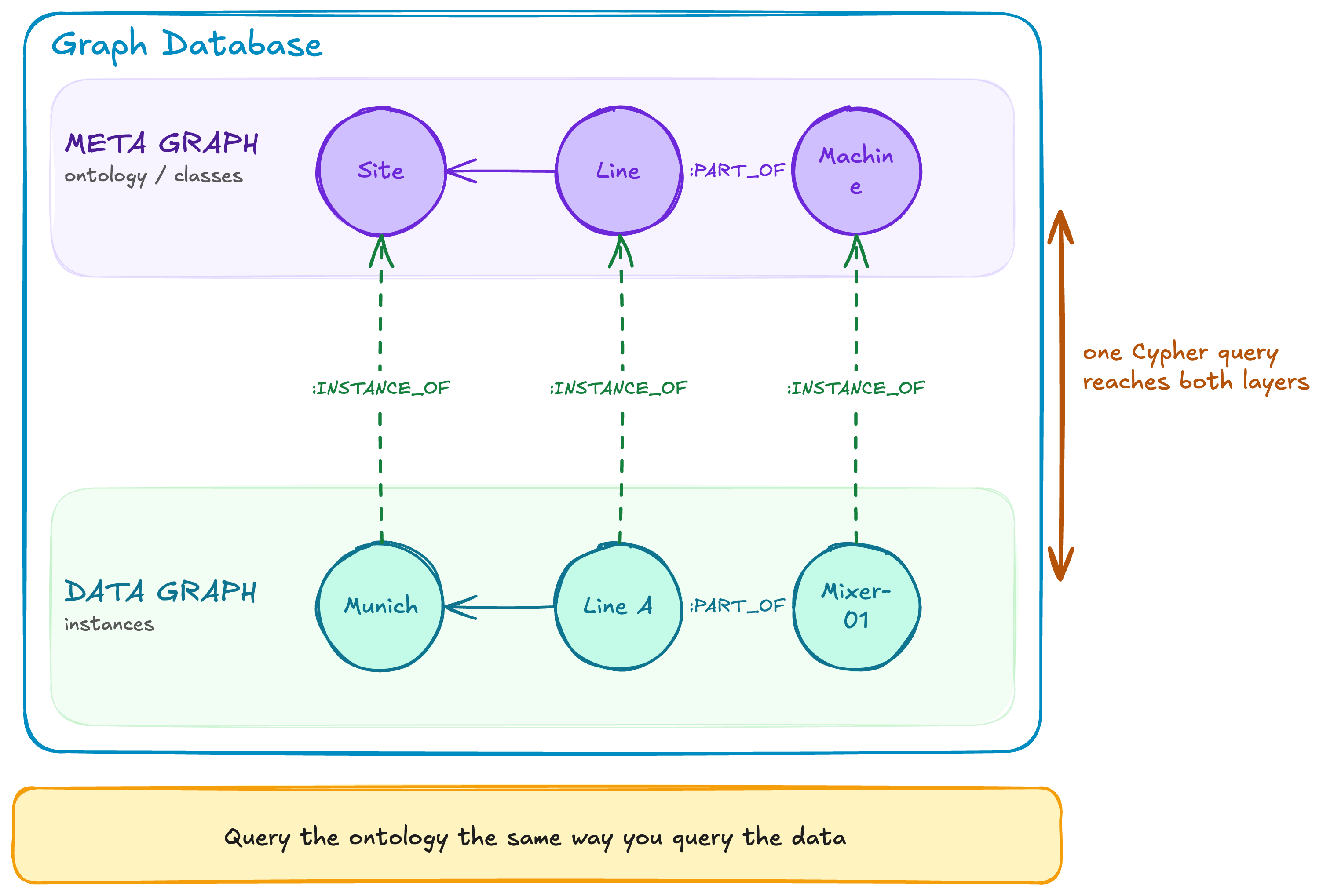
The advantage of this approach is that you can navigate both the ontology and the operational data using the same query language.
For example, a question such as, Give me all the rotating equipment located under Site A, can be expressed as a Cypher query that starts with the Rotating Equipment concept, traverses its subclasses, and ultimately returns the real equipment instances deployed at Site A.
This is the approach we will use. We will represent our ontology as a metagraph in Neo4j. Later, we will populate the database with operational data and link each real-world entity to the relevant concepts in the metagraph, creating a Knowledge Graph that connects semantic definitions with operational reality.
Before we do that, however, we need to understand the data model used by modern graph databases such as Neo4j. This model provides the basic structure for representing both the ontology and the operational data connected to it.
The Property Graph Data Model
Modern graph databases such as Neo4j use what is known as the property graph data model. At its core, this model is built around two main elements: nodes and relationships.
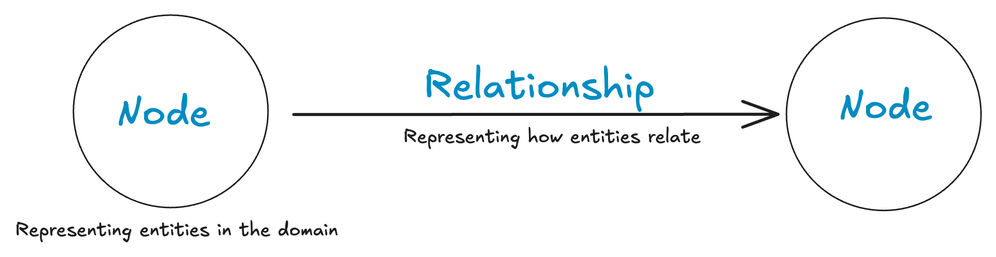
Nodes represent entities within a domain. In manufacturing, a node might represent an asset, machine, production line, material, work order, operator, or site. Each node can have zero or more properties. Properties are key-value pairs that store information about the entity, such as its name, serial number, status, installation date, or unique identifier.
Nodes can also have one or more labels. Labels classify nodes according to what they represent. For example, a node might be labelled Asset, Machine, or Site. Where appropriate, a single node can have multiple labels.
Relationships describe how nodes are connected to one another.
Each relationship has a type that defines the meaning of the connection, such as BOUGHT, MEASURES, FEEDS, or SUBCLASS_OF. In this way, relationships do more than simply connect two nodes; they describe the nature of the connection between them.
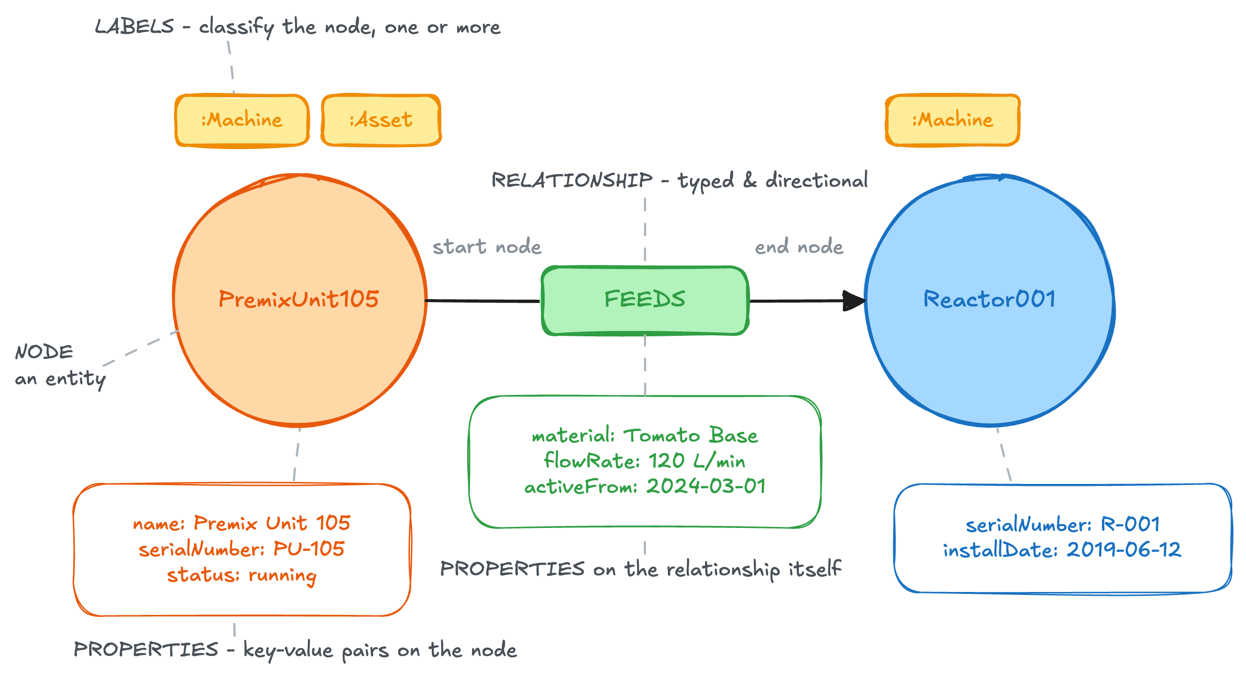
Relationships are also directional. They run from a start node to an end node, although the relationship can still be queried in either direction. A relationship may also connect a node back to itself.
Like nodes, relationships can carry properties. These might include a timestamp, duration, distance, confidence score, sequence number, or any other information that describes the connection itself.
For example, a FEEDS relationship between two process units might contain properties describing the material being transferred, the normal flow rate, or the date on which the connection became active.
Using just these basic building blocks, nodes, labels, properties, and relationships, you can represent detailed, interconnected operational data in a graph database.
The same building blocks can be used to model the ontology itself, not just the operational data underneath it. That's what we mean by ontology as a meta graph: a graph whose nodes and edges describe the shape of another graph.
Creating a Basic Ontology in Neo4j Cypher
Below is a simple Cypher query that creates a small ontology containing three classes: Asset, Compressor, and Sensor.
It also defines two relationships:
- A
Compressoris a subclass of anAsset. - A
Sensormeasures aCompressor.
CREATE (asset:Class {name: 'Asset'})
CREATE (compressor:Class {name: 'Compressor'})
CREATE (sensor:Class {name: 'Sensor'})
CREATE (compressor)-[:SUBCLASS_OF]->(asset)
CREATE (sensor)-[:MEASURES]->(compressor)
Each ontology class, the abstract concept of an Asset, Compressor, or Sensor, is represented as a node.
We give each of these nodes the label Class so that we can distinguish ontology definitions from the operational data that will eventually instantiate them.
The relationships permitted by the ontology are represented as typed relationships between these Class nodes. In this example, SUBCLASS_OF expresses that every compressor is a type of asset, while MEASURES expresses that a sensor can measure a compressor.
The actual operational entities, such as Compressor07, the Pressure_Sensor will exist as a separate layer of nodes. These instance nodes can then be linked to their class definitions through relationships such as INSTANCE_OF.
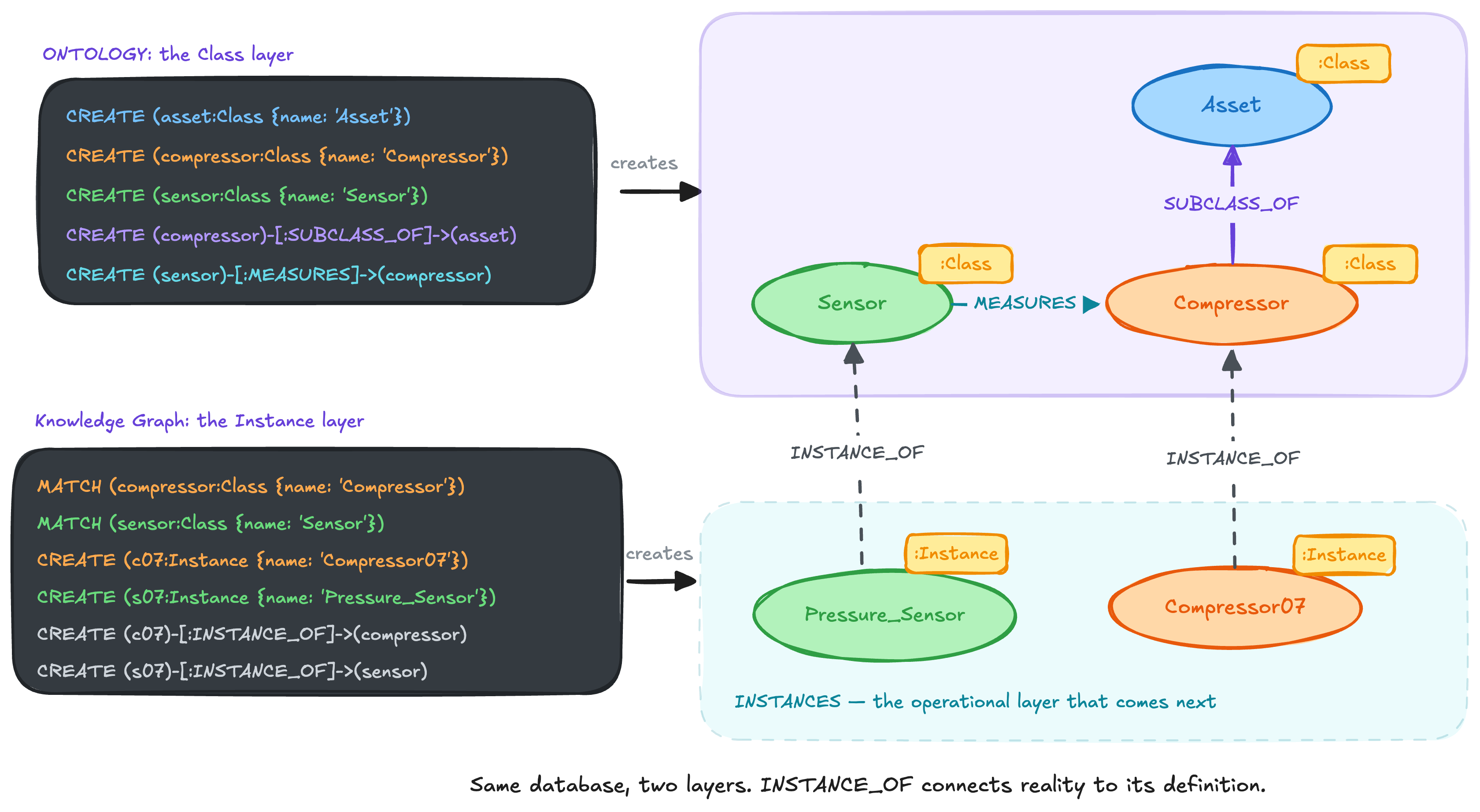
Although this is a small example, it demonstrates the central idea: the graph is not only storing operational data. It is also storing the definitions, classifications, relationships, and rules that give that data meaning.
What we have built so far is intentionally simple. Now, let’s use those mechanics to create an ontology that is genuinely useful for manufacturing operations.
Creating the core manufacturing ontology concepts in Neo4j
In this section, we'll create an ontology modelling nine core manufacturing operations concepts: PROCESS, PHYSICAL ENTITY, OPERATIONAL ENTITY, AGENT, LOCATION, CAPABILITY, ROLE, EVENT, and STATE.
You can refer to this article for a more detailed explanation of these concepts. However, understanding them is not a prerequisite for following this article. The objective here is to demonstrate how to create an ontology in Neo4j, and the same approach applies regardless of the specific concepts you choose to model.
Creating Process Class
This creates Process as the general concept for work that unfolds over time.
MERGE (c:Class {
   uri: 'http://industry40.tv/ontology/core/Process'
})
ON CREATE SET c.created_at = datetime()
SET c:Core,
   c.name = 'Process',
   c.description = 'Work that happens over time and creates, transforms, moves, inspects, maintains, or otherwise affects something. A process may contain subprocesses and may be executed manually, automatically, or through a combination of people, equipment and software.',
   c.examples = [
       'Mixing',
       'Welding',
       'Packaging',
       'Inspection',
       'Cleaning',
       'Material transfer'
   ],
   c.version = '1.0.0';
Creating PhysicalEntity Class
PhysicalEntity describes physical things that exist in the manufacturing environment.
MERGE (c:Class {
   uri: 'http://industry40.tv/ontology/core/PhysicalEntity'
})
ON CREATE SET c.created_at = datetime()
SET c:Core,
   c.name = 'PhysicalEntity',
   c.description = 'A physical entity that exists within the manufacturing environment. Describes what something IS, not the role it plays in a particular process.',
   c.examples = [
       'Material',
       'Product',
       'Equipment',
       'Tool',
       'Container',
       'Sample'
   ],
   c.version = '1.0.0';
Creating OperationalEntity Class
An OperationalEntity is an informational object involved in manufacturing operations.
MERGE (c:Class {
   uri: 'http://industry40.tv/ontology/core/OperationalEntity'
})
ON CREATE SET c.created_at = datetime()
SET c:Core,
   c.name = 'OperationalEntity',
   c.description = 'An informational object that directs, constrains, describes, or records operational work. Divides broadly into entities that describe intended work and entities that provide evidence of completed work.',
   c.examples = [
       'Order',
       'Schedule',
       'Recipe',
       'Procedure',
       'Specification',
       'Work instruction',
       'Production record',
       'Inspection result'
   ],
   c.version = '1.0.0';
Creating Agent Class
An Agent is anything capable of intentional, autonomous, or delegated participation in operational work. An agent does not necessarily perform the physical transformation itself. It may supervise a process, coordinate resources, control equipment, approve work, observe execution, recommend an action, or make a decision
MERGE (c:Class {
   uri: 'http://industry40.tv/ontology/core/Agent'
})
ON CREATE SET c.created_at = datetime()
SET c:Core,
   c.name = 'Agent',
   c.description = 'Something capable of participating in, controlling, or making decisions about a process. It may supervise, coordinate, control, approve, or decide rather than perform the physical transformation itself.',
   c.examples = [
       'Personnel',
       'Team',
       'Equipment controller',
       'Software application',
       'AI agent'
   ],
   c.version = '1.0.0';
Location
Location provides the spatial context in which entities exist and processes occur.
MERGE (c:Class {
   uri: 'http://industry40.tv/ontology/core/Location'
})
ON CREATE SET c.created_at = datetime()
SET c:Core,
   c.name = 'Location',
   c.description = 'Where an entity, agent, or process exists or occurs. The ISA-95 equipment hierarchy extends this concept.',
   c.examples = [
       'Enterprise',
       'Site',
       'Area',
       'Work center',
       'Work unit'
   ],
   c.version = '1.0.0';
Creating Capability Class
A capability describes what something can do independently of what it is currently doing. For example:
MERGE (c:Class {
   uri: 'http://industry40.tv/ontology/core/Capability'
})
ON CREATE SET c.created_at = datetime()
SET c:Core,
   c.name = 'Capability',
   c.description = 'What an entity, agent, or organizational unit is able to do. Separates what a resource CAN DO from the process it is currently executing; may carry constraints or parameters.',
   c.examples = [
       'Mixing capability',
       'Filling capability',
       'Temperature-measurement capability',
       'Sterilization capability',
       'Inspection capability'
   ],
   c.version = '1.0.0';
Mixer101 HAS_CAPABILITY MixingCapability
This statement may remain true even while Mixer101 is idle.
Separating capability from current execution enables several operational use cases:
- Resource selection
- Scheduling
- Substitution
- Qualification checking
- Capacity planning
- AI-assisted work assignment
A process can state what capability it requires without referring to a particular resource:
MixingProcess REQUIRES_CAPABILITY MixingCapability
The knowledge graph can then be queried for entities that possess that capability.
Creating Role Class
Role captures contextual participation. The same entity may play different roles in different processes.
MERGE (c:Class {
   uri: 'http://industry40.tv/ontology/core/Role'
})
ON CREATE SET c.created_at = datetime()
SET c:Core,
   c.name = 'Role',
   c.description = 'How an entity participates in a particular process or relationship. The same entity may play different roles in different contexts, so a role is interpreted within a context rather than as a permanent classification.',
   c.examples = [
       'Input',
       'Output',
       'Performer',
       'Observer',
       'Controller',
       'Consumer',
       'Producer'
   ],
   c.version = '1.0.0';
Creating Event Class
Events provide the time-based evidence of manufacturing operations. They allow us to represent not only static facts but what occurred:
MixingStartedEvent
MaterialConsumedEvent
EquipmentFailureEvent
InspectionCompletedEvent
BatchReleasedEvent
Events are particularly important for analytics, traceability, root-cause investigation, and AI-agent reasoning because they connect operational facts to time.
MERGE (c:Class {
   uri: 'http://industry40.tv/ontology/core/Event'
})
ON CREATE SET c.created_at = datetime()
SET c:Core,
   c.name = 'Event',
   c.description = 'Something operationally significant that occurred at a particular point or interval in time. Provides the time-based operational evidence needed for analytics, traceability, and agentic decision-making.',
   c.examples = [
       'Process started',
       'Order released',
       'Material consumed',
       'Alarm activated',
       'Inspection completed',
       'Equipment failed'
   ],
   c.version = '1.0.0';
Creating State Class
A state describes a condition that holds during a period of time.
MERGE (c:Class {
   uri: 'http://industry40.tv/ontology/core/State'
})
ON CREATE SET c.created_at = datetime()
SET c:Core,
   c.name = 'State',
   c.description = 'The condition of an entity or process during a period of time. Events usually cause or indicate state changes.',
   c.examples = [
       'Running',
       'Idle',
       'Failed',
       'Available',
       'In production',
       'Awaiting inspection',
       'Released',
       'Quarantined'
   ],
   c.version = '1.0.0';
Creating subclasses of the core ontology concepts
The nine concepts are deliberately abstract. They are not the vocabulary you use to describe a real plant, nobody commissions a "PhysicalEntity" or schedules work at a "Location".
That is by design. The ontology grows by subclassing the nine concepts rather than by adding new ones. SUBCLASS_OF is the mechanism, and keeping the concept count fixed is what stops the core from sprawling as new domains arrive.
Most of that subclassing happens later, in the domain extensions: a production ontology adds Filler and RawMaterial, a maintenance ontology adds ConditionSensor, and each attaches to a core concept with SUBCLASS_OF.
But two sets of subclasses belong in the core itself, because every domain needs them:
- The ISA-95 equipment hierarchy model, so every domain locates work against the same spatial vocabulary.
- The physical entity tier, so every domain classifies physical things the same way.
Each is created the same way: a Class node, then a SUBCLASS_OF edge to its parent concept.
The ISA-95 Hierarchy Model
Location on its own is too coarse to schedule or report against. Every manufacturing domain needs the same spatial vocabulary, and ISA-95 already provides it: an enterprise owns sites, a site divides into areas, an area contains work centres.
These four levels are created as subclasses of Location:
MERGE (c:Class {
   uri: 'http://industry40.tv/ontology/core/Enterprise'
})
ON CREATE SET c.created_at = datetime()
SET c:Core,
   c.name = 'Enterprise',
   c.description = 'The organization or business entity that owns and operates one or more sites. The top of the ISA-95 spatial hierarchy.',
   c.examples = ['Global Industries'],
   c.version = '1.0.0';

MERGE (c:Class {
   uri: 'http://industry40.tv/ontology/core/Site'
})
ON CREATE SET c.created_at = datetime()
SET c:Core,
   c.name = 'Site',
   c.description = 'A physical location where operations are conducted, such as a manufacturing plant. Belongs to an Enterprise and is divided into Areas.',
   c.examples = [
       'Munich Plant',
       'Dallas Plant'
   ],
   c.version = '1.0.0';

MERGE (c:Class {
   uri: 'http://industry40.tv/ontology/core/Area'
})
ON CREATE SET c.created_at = datetime()
SET c:Core,
   c.name = 'Area',
   c.description = 'A functional division of a site that groups the work centres serving a common purpose. Domain extensions specialise it (ProductionArea, PackagingArea, UtilitiesArea, Warehouse).',
   c.examples = [
       'Production Area',
       'Packaging Area',
       'Utilities Area',
       'Raw Material Storage Area'
   ],
   c.version = '1.0.0';

MERGE (c:Class {
   uri: 'http://industry40.tv/ontology/core/WorkCenter'
})
ON CREATE SET c.created_at = datetime()
SET c:Core,
   c.name = 'WorkCenter',
   c.description = 'A location within an area where work is performed — a production line, packaging line, storage zone, or utility system. The finest shared spatial grain; equipment is located at a work centre. Domain extensions specialise it (ProductionLine, PackagingLine, StorageZone).',
   c.examples = [
       'Production Line 1',
       'Packaging Line 1',
       'Dry Ingredient Storage',
       'Steam System'
   ],
   c.version = '1.0.0';

All four attach to Location in one statement:

MATCH (loc:Class {name: 'Location'})
MATCH (c:Class)
WHERE c.name IN ['Enterprise', 'Site', 'Area', 'WorkCenter']
MERGE (c)-[:SUBCLASS_OF]->(loc);
Two decisions here are worth stating explicitly, because both are easy to get wrong.
These are levels, not containers. It is tempting to model the hierarchy by subclassing, to say a Site is a subclass of an Enterprise. That would be wrong. A site is not a kind of enterprise; it is a thing contained by one. Subclassing describes what something IS, while containment describes how instances nest. So the four are siblings under Location, and the actual nesting is asserted between instances using the CONTAINS relationship:
Work Unit is deliberately omitted. ISA-95 defines a fifth level below the work centre, but in most cases a physical asset fills that role; the filler on a packaging line is the work unit. Adding a separate WorkUnit level would create a redundant one-to-one location node above every asset. Instead, equipment attaches directly to its work centre through IS_LOCATED_AT.
Domain extensions then specialize Area and WorkCenter into concrete types, ProductionArea, PackagingArea, Warehouse, ProductionLine, PackagingLine, StorageZone, each with its own SUBCLASS_OF edge to the core level it refines.
The physical entity tier
PhysicalEntity needs the same treatment for the same reason. On its own, it groups everything physical in the plant into one undifferentiated bucket, from a boiler to a bottle cap.
Every physical thing divides on a single question: does the plant operate it, or does it flow through? A filler, a boiler and a pH meter are installed, operated and maintained. A raw ingredient, a closure and a sample are consumed, transformed or dispatched. That distinction gives two subclasses:
MERGE (c:Class {
   uri: 'http://industry40.tv/ontology/core/Equipment'
})
ON CREATE SET c.created_at = datetime()
SET c:Core,
   c.name = 'Equipment',
   c.description = 'A physical asset the plant installs, operates and maintains in order to carry out work — it transforms, moves, packages, measures, stores or services something, rather than being consumed by the process itself. Located at a Work Center, and the entity that equipment states, modes, metrics and maintenance are asserted against. Domain extensions specialise it into concrete asset types.',
   c.examples = [
       'Filler',
       'Cook Kettle',
       'Boiler',
       'Energy Meter',
       'pH Meter',
       'Condition Sensor',
       'Storage Tank',
       'Torque Wrench'
   ],
   c.version = '1.0.0';

MERGE (c:Class {
   uri: 'http://industry40.tv/ontology/core/Material'
})
ON CREATE SET c.created_at = datetime()
SET c:Core,
   c.name = 'Material',
   c.description = 'A kind of physical stuff that flows through the plant — consumed as input, carried through the process, packaged into the product, drawn off for test, or held to service an asset. Material is a DEFINITION, not a quantity: it answers what kind of stuff this is, while a tracked quantity of it is a MaterialLot related by IS_QUANTITY_OF. Domain extensions specialise it into concrete material types.',
   c.examples = [
       'Raw Material',
       'Intermediate Product',
       'Finished Product',
       'Primary Container',
       'Closure',
       'Label',
       'Shipping Case',
       'Sample',
       'Spare Part'
   ],
   c.version = '1.0.0';

MATCH (pe:Class {name: 'PhysicalEntity'})
MATCH (c:Class)
WHERE c.name IN ['Equipment', 'Material']
MERGE (c)-[:SUBCLASS_OF]->(pe);
Note the symmetry with the location tier. Location gains structural levels; PhysicalEntity gains a physical classification. In both cases the core supplies a shared vocabulary and the domain extensions specialise it, Filler and Boiler under Equipment, RawMaterial and Closure under Material, exactly as ProductionArea sits under Area.
The general rule: use SUBCLASS_OF only when the child genuinely IS a kind of the parent. When the connection is "quantity of", "grouping of", or "contained by", it belongs in a relationship.
The state scopes
State needs dividing for the same reason Location and PhysicalEntity do. Left flat, a vocabulary of conditions cannot say whose lifecycle a state belongs to, so nothing prevents a work order being Running or a filler being Completed.
The core therefore divides it five ways:
MATCH (s:Class {name: 'State'})
MATCH (c:Class)
WHERE c.name IN
 ['EquipmentState', 'ProcessState', 'OrderState', 'WorkOrderState', 'MaterialState']
MERGE (c)-[:SUBCLASS_OF]->(s);
The resulting hierarchy
After this section the core contains twenty classes: the nine concepts, the four location levels, the two physical entity subclasses, and the five state scopes, with the subclassing forming three small trees:
The remaining six concepts, Process, OperationalEntity, Agent, Capability, Role and Event, have no core subclasses. They are specialised directly by the domain extensions.
Everything a domain extension adds from here attaches to one of these twenty nodes.
Creating the core relationship definitions
The core ontology defines the following relationship vocabulary:
AFFECTS, PARTICIPATES_IN, PLAYS_ROLE, HAS_CAPABILITY, REQUIRES_CAPABILITY, IS_GUIDED_BY, PRODUCES, OCCURS_AT, IS_LOCATED_AT, OCCURS_DURING, CHANGES_STATE, TRANSITIONS_TO, TRANSITIONS_FROM, HAS_STATE, HAS_SUBPROCESS, and CONTAINS.
Below is an example of how to define the PARTICIPATES_IN relationship type in Neo4j. You can use the same approach to create the remaining relationship types in your ontology vocabulary.
MERGE (r:Relationship {
   uri: 'http://industry40.tv/ontology/core/rel/PARTICIPATES_IN'
})
ON CREATE SET r.created_at = datetime()
SET r:Core,
   r.name = 'PARTICIPATES_IN',
   r.description = 'An entity is involved in the execution of a process. Participation alone does not explain HOW the entity is involved — that is expressed through a Role.',
   r.examples = [
       'Mixer PARTICIPATES_IN MixingExecution',
       'Operator PARTICIPATES_IN MixingExecution',
       'MaterialLot PARTICIPATES_IN MixingExecution'
   ],
   r.version = '1.0.0';
Defining relationship domains
Once you have defined the relationships in your ontology, you need to specify how each one may be used. We begin with the domain, which identifies the kinds of concepts that may appear on the starting side of a relationship. For example, defining Process as the domain of OCCURS_AT tells us that it is a process, not a state, capability, or operational record, that may occur at a location.
For example:
MATCH
   (r:Relationship {name: 'OCCURS_AT'}),
   (c:Class {name: 'Process'})
MERGE (r)-[:HAS_DOMAIN]->(c);
This creates:
OCCURS_AT HAS_DOMAIN Process
The ontology therefore says that a process is the kind of thing that occurs at a location.
Some relationships support more than one domain.
For example, both a process and an event can affect an entity:
MATCH
   (r:Relationship {name: 'AFFECTS'}),
   (c:Class {name: 'Process'})
MERGE (r)-[:HAS_DOMAIN]->(c);

MATCH
   (r:Relationship {name: 'AFFECTS'}),
   (c:Class {name: 'Event'})
MERGE (r)-[:HAS_DOMAIN]->(c);
The resulting definition is:
AFFECTS HAS_DOMAIN Process
AFFECTS HAS_DOMAIN Event
Multiple HAS_DOMAIN relationships are interpreted here as an allowed union: the source may be any one of the connected classes.
HAS_STATE, for instance, may originate from a process or from any of the three concepts that describe things, so it names all four:
Naming each class rather than grouping them under a shared parent is what lets each domain be exactly as wide as the relationship needs. HAS_CAPABILITY, for example, accepts only two of the four:
HAS_CAPABILITY HAS_DOMAIN PhysicalEntity
HAS_CAPABILITY HAS_DOMAIN Agent
A mixer has a capability and so does an operator, but a work order does not. The same applies to IS_LOCATED_AT, PARTICIPATES_IN and PLAYS_ROLE: they describe things that physically take part in work, which an informational object does not do. Informational objects relate to work through IS_GUIDED_BY and PRODUCES instead.
Naming each class costs a few more edges than a shared parent would, but it keeps every domain exactly as wide as the relationship it describes.
Defining relationship ranges
After defining where each relationship may start, we need to define where it may point. The range identifies the kinds of concepts permitted on the target side of a relationship. For example, defining Location as the range of OCCURS_AT completes the statement that a Process OCCURS_AT Location. Together, the domain and range give the relationship its complete semantic structure.
For example:
MATCH
(r:Relationship {name: 'OCCURS_AT'}),
(c:Class {name: 'Location'})
MERGE (r)-[:HAS_RANGE]->(c);
This creates:
OCCURS_AT HAS_RANGE Location
In the previous section, we defined Process as the domain of OCCURS_AT. Combining that domain with the range now gives us the complete semantic signature:
Process OCCURS_AT Location
The ontology therefore defines both where the relationship may start and where it may point: a process may occur at a location.
The same pattern is used for the rest of the relationship vocabulary. Where a side lists more than one class, each is a separate HAS_DOMAIN or HAS_RANGE edge and any one of them is permitted:
Notice that the four "taking part in work" relationships, PARTICIPATES_IN, PLAYS_ROLE, HAS_CAPABILITY, IS_LOCATED_AT, accept PhysicalEntity and Agent but not OperationalEntity, while HAS_STATE, AFFECTS and CHANGES_STATE accept all three. That asymmetry is the point of declaring domains per relationship: each one is exactly as wide as the statement it licenses.
These signatures become semantic guidance for applications that create or validate the knowledge graph.
Domain and range are descriptive
It is important to understand what the domain and range model does, and what it does not do.
Creating:
PARTICIPATES_IN HAS_DOMAIN PhysicalEntity
PARTICIPATES_IN HAS_RANGE Process
does not automatically prevent someone from creating an invalid operational relationship such as:
LocationA PARTICIPATES_IN StateB
The domain and range are represented as ontology data. They describe the valid use of the relationship, but they are not automatically enforced against every arbitrary relationship written to the database.
The application or ingestion layer should therefore consult the ontology before creating instance relationships.
Conceptually, the ingestion flow becomes:
This is also valuable for AI agents. Before generating or proposing a graph update, an agent can retrieve the relationship definition and verify that the proposed source and target classes are semantically compatible.
Visualize the ontology graph
Once you have created your ontology as a metagraph in neo4j, you can query the ontology to confirm what was created by listing the core classes, viewing the class hierarchy, displaying domains and ranges, or visualizing the ontology graph. For example, the entire core model can be returned as a graph:
MATCH path =
   (domain:Class)<-[:HAS_DOMAIN]-
   (relationship:Relationship)
   -[:HAS_RANGE]->(range:Class)
RETURN path;A separate query can return the concept hierarchy:
MATCH path = (:Class)-[:SUBCLASS_OF]->(:Class)
RETURN path;
MATCH path = (:Class)-[:SUBCLASS_OF]->(:Class)
RETURN path;
This gives you a visual model consisting of:
- Class nodes
- Relationship-definition nodes
- Domain connections
- Range connections
- Subclass connections
Conclusion
The implementation shown in this article turns the Core Manufacturing Ontology from a conceptual specification into a machine-readable Neo4j graph. The resulting model is small enough to remain understandable and governable, but expressive enough to provide a shared semantic foundation across production, maintenance, quality, inventory, and other manufacturing domains.
More importantly, it creates a formal structure that people, applications, analytics, and AI agents can use to interpret operational data consistently.
In the next article, we extend this core ontology to create a production domain ontology.
Get the Next Guide
New architecture guides, implementation tutorials and use-case blueprints, delivered as they’re published.
More guides
All guides →

The leading IIoT & AI educational platform for digital manufacturing teams