
Building an Energy Operations Domain Ontology in Manufacturing
The core manufacturing ontology already gives us shared concepts. Here we extend it with the classes and relationships needed to describe energy and plant utilities.

In the previous articles, we defined a small core manufacturing ontology and extended it with the concepts required to describe production, quality, maintenance, and inventory operations.
The same approach can be applied to energy and plant utilities.
The core ontology already provides the general concepts shared across manufacturing operations: Process, PhysicalEntity, OperationalEntity, Agent, Location, Capability, Role, Event, and State.
What it deliberately does not define are energy-specific concepts such as boilers, electricity meters, steam, energy tariffs, demand management, or peak-demand events.
Those belong in an energy-domain ontology.
The purpose of the energy ontology is therefore to add the vocabulary required to describe how utilities are generated, distributed, measured, consumed, and managed across manufacturing operations, while keeping those concepts connected to the shared manufacturing core.
In this example, the ontology covers electricity, steam, compressed air, cooling water, utility equipment, metering, electrical-demand management, tariffs, and energy-significant events.
Extending the Core Ontology
As with the other domain extensions, energy concepts are introduced by specializing concepts that already exist in the core.
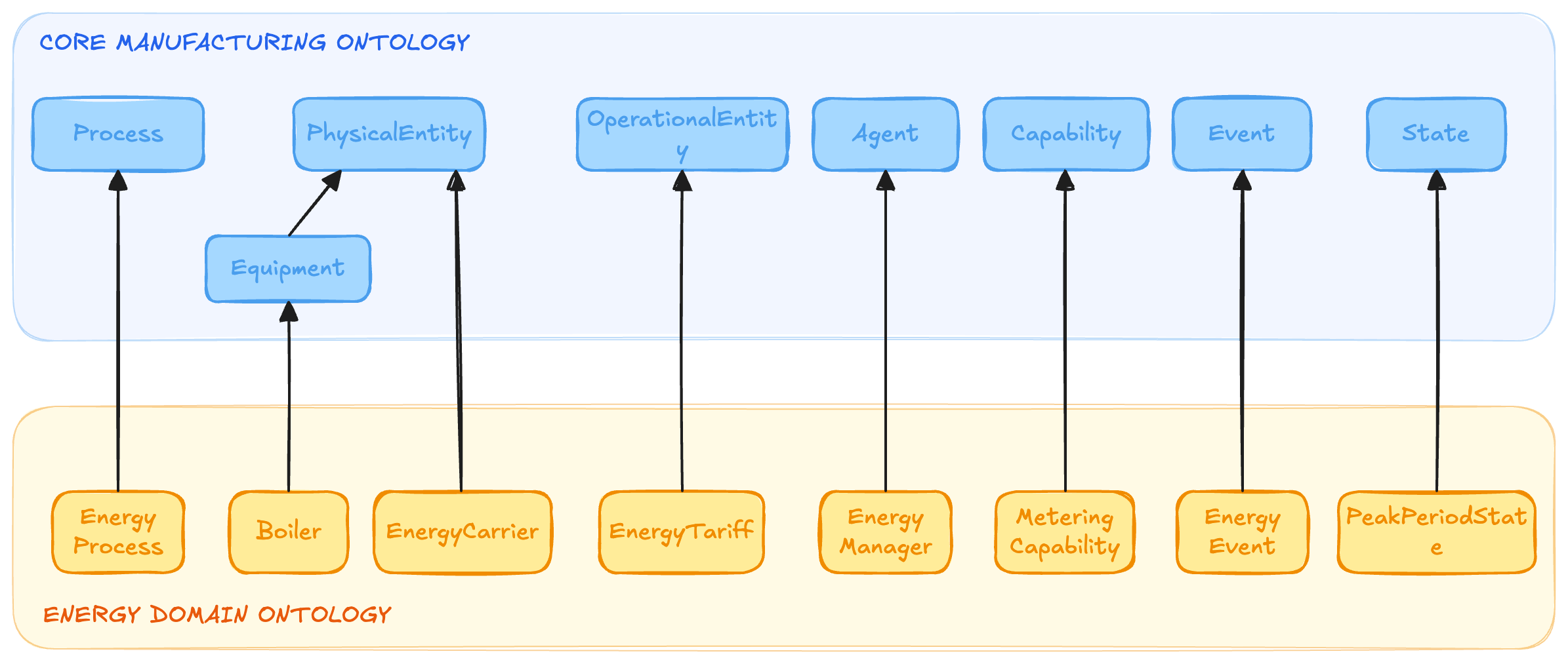
For example:
EnergyProcess SUBCLASS_OF Process
Boiler SUBCLASS_OF Equipment
EnergyCarrier SUBCLASS_OF PhysicalEntity
EnergyTariff SUBCLASS_OF OperationalEntity
EnergyManager SUBCLASS_OF Agent
MeteringCapability SUBCLASS_OF Capability
EnergyEvent SUBCLASS_OF Event
PeakPeriodState SUBCLASS_OF State
The core remains unchanged. It provides the general semantic structure, while the energy ontology introduces the concepts required to describe plant utilities and how they are consumed and managed.
This produces hierarchies such as:
PhysicalEntity
    ├── Equipment
    │     ├── EnergyMeter
    │     ├── PowerMeter
    │     ├── Boiler
    │     ├── CoolingSystem
    │     └── CompressedAirSystem
    │
    └── EnergyCarrier
          ├── Electricity
          ├── Steam
          ├── CompressedAir
          └── CoolingWater
The domain becomes more precise without changing the meaning of the core concepts it extends.
Utility Locations and Equipment
The core already provides the ISA-95 location levels Enterprise, Site, Area, and WorkCenter. The energy ontology can therefore introduce:
UtilitiesArea SUBCLASS_OF Area
MeteringPoint SUBCLASS_OF Location
A UtilitiesArea represents the part of the site responsible for utility generation and distribution, such as steam, compressed air, cooling water, or electrical infrastructure.
MeteringPoint is slightly different. A metering point may refer to a precise position in a utility network rather than an ISA-95 organizational level, so it attaches directly to Location.
For example:
PlantUtilitiesArea INSTANCE_OF UtilitiesArea
PackagingLinePowerPoint INSTANCE_OF MeteringPoint

Boiler IS_LOCATED_AT PlantUtilitiesArea
PackagingPowerMetering OCCURS_AT PackagingLinePowerPoint
The distinction between a meter and a metering point is useful. The meter is the physical device; the metering point identifies where in the utility network the measurement applies.
Utility assets themselves specialize the core Equipment class:
EnergyMeter SUBCLASS_OF Equipment
PowerMeter SUBCLASS_OF Equipment
Boiler SUBCLASS_OF Equipment
CoolingSystem SUBCLASS_OF Equipment
CompressedAirSystem SUBCLASS_OF EquipmentAn EnergyMeter may measure steam, gas, compressed air, or cooling-water consumption. A PowerMeter measures electrical power, demand, and energy. Boilers generate steam, cooling systems remove heat, and compressed-air systems provide pneumatic energy to plant equipment.
Actual assets then become instances:
SteamMeter12 INSTANCE_OF EnergyMeter
PackagingLinePowerMeter INSTANCE_OF PowerMeter
Boiler1 INSTANCE_OF Boiler
CompressedAirPlant1 INSTANCE_OF CompressedAirSystem
Representing Energy Carriers
One of the most important additions in the energy ontology is:
EnergyCarrier SUBCLASS_OF PhysicalEntity
An EnergyCarrier represents a medium through which usable energy is delivered to a manufacturing process.
Typical subclasses include: Electricity, Steam, CompressedAir, and CoolingWater
Electricity powers motors, controls, and production equipment. Steam provides thermal energy for cooking, heating, and cleaning. Compressed air drives pneumatic valves and actuators. Cooling water removes heat from products and equipment.
Representing these as physical entities allows them to participate in operational relationships just like other things in the plant.
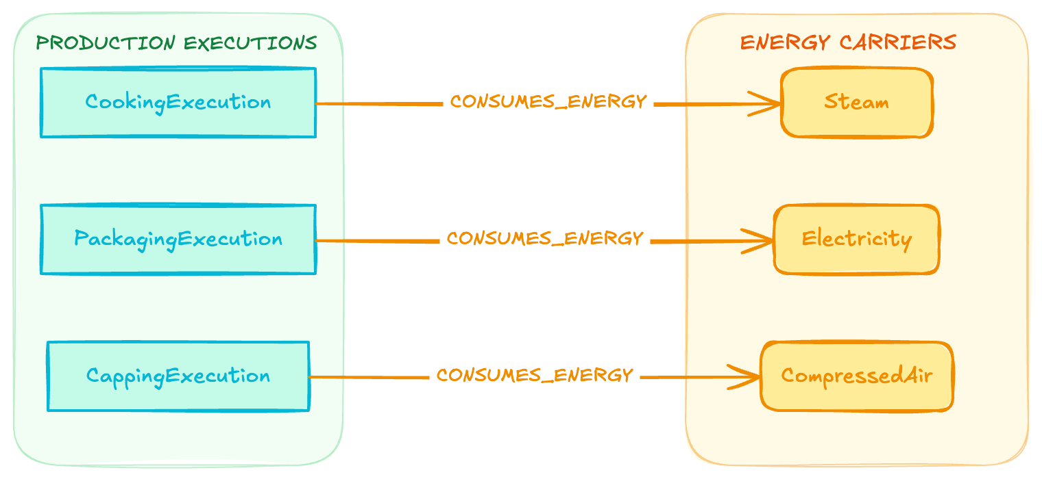
For example:
CookingExecution CONSUMES_ENERGY Steam
PackagingExecution CONSUMES_ENERGY Electricity
CappingExecution CONSUMES_ENERGY CompressedAirThis is much more useful than treating energy consumption as an isolated meter reading. It connects the utility being consumed directly to the production activity responsible for consuming it.
Defining Energy Processes
The energy ontology introduces:
EnergyProcess SUBCLASS_OF Process
and specializes it into three important forms of energy-management work:
EnergyMetering
DemandManagement
LoadShedding
EnergyMetering represents measuring and recording consumption at a defined metering point.
For example:
PackagingPowerMetering88 INSTANCE_OF EnergyMetering
The process may read a meter, associate the reading with its location, calculate interval consumption, and publish that measurement to an energy-monitoring system.
DemandManagement represents coordinating electrical loads to keep total plant demand within an acceptable limit. That limit might come from a contractual maximum, an internal target, the current billing-period peak, or a demand-charge threshold.
If demand approaches that limit, the plant may initiate LoadShedding, which represents deliberately reducing or postponing non-critical loads.
The resulting sequence might be:
EnergyMetering → DemandManagement → Demand limit exceeded → LoadShedding
This makes energy management part of the operational model rather than treating energy only as something reported after production has finished.
Representing Tariffs, Budgets, and Energy Evidence
Energy consumption also has a commercial and managerial context.
The energy ontology therefore extends OperationalEntity with concepts such as:
EnergyTariff - defines how energy is priced, including peak, off-peak, or time-of-use periods.
DemandChargeRate
EnergyBudget
EnergyReport
These entities can guide or result from energy processes:
PlantDemandManagement12
   IS_GUIDED_BY PlantElectricityTariff2026

PlantDemandManagement12
   IS_GUIDED_BY MonthlyDemandCharge2026

PlantEnergyAnalysisJuly
PRODUCES JulyEnergyPerformanceReportThis creates an important distinction between the rules and targets governing energy use and the evidence describing what actually happened.
That distinction becomes particularly useful when operational decisions depend not only on how much energy is being consumed, but also on what that consumption costs at a particular time.
Agents and Capabilities
The energy ontology can also introduce specialized agents:
EnergyManager SUBCLASS_OF Agent
EnergyMonitoringSystem SUBCLASS_OF AgentAn EnergyManager may participate in budgeting, performance review, demand management, or load-shedding decisions. An EnergyMonitoringSystem collects meter readings, tracks demand, and identifies when consumption approaches defined limits.
Their abilities can be represented separately through capabilities: MeteringCapability and DemandControlCapability
For example:
PackagingLinePowerMeter
   HAS_CAPABILITY MeteringCapability

EnergyMetering
   REQUIRES_CAPABILITY MeteringCapability

PlantEnergyMonitoringSystem
   HAS_CAPABILITY DemandControlCapability

DemandManagement
REQUIRES_CAPABILITY DemandControlCapabilityAs in the other domains, this separates what a system or device is from what it is capable of doing. An application or AI agent can therefore identify which meters can provide a required measurement or which systems can participate in demand-control activities.
Defining Energy Events and Tariff States
The energy ontology extends the core Event concept with significant occurrences such as: MeterReadingTaken, PeakDemandReached, TariffChanged, and DemandLimitExceeded
For example:
MeterReadingEvent INSTANCE_OF MeterReadingTaken
MeterReadingEvent OCCURS_DURING PackagingPowerMeteringIf plant demand exceeds its target:
DemandLimitExceededEvent31 INSTANCE_OF DemandLimitExceeded
DemandLimitExceededEvent31 OCCURS_DURING PlantDemandManagement12That event may trigger a load-shedding process.
The ontology also needs to represent pricing periods: PeakPeriodState and OffPeakPeriodState
These are unusual because they do not naturally belong to the existing state scopes such as EquipmentState, ProcessState, or MaterialState.
A tariff period is a condition of the energy-pricing context rather than the lifecycle of a machine, process, order, or material. It therefore makes sense to attach these directly to the core State concept.
For example:
PeakTariffStartedEvent CHANGES_STATE PlantElectricitySupply
PlantElectricitySupply HAS_STATE PeakPeriodStateThis matters because the same amount of electricity can have very different financial consequences depending on when it is consumed. An energy-management agent can therefore reason not only about current demand, but also about whether that demand is occurring during a high-cost pricing period.
Specializing Core Relationships
The energy ontology also makes broad core relationships more precise.
The core defines:
Process AFFECTS Entity
Energy can specialize this with:
CONSUMES_ENERGY
For example:
CookingExecution4711 CONSUMES_ENERGY Steam
PackagingExecution882 CONSUMES_ENERGY ElectricityThis tells us specifically how the process affects the energy carrier.
A second useful relationship is:
METERED_BY
For example:
PackagingExecution882
   METERED_BY PackagingLinePowerMeter

Steam
METERED_BY SteamMeter12There is, however, an important modeling issue here. In the current implementation, METERED_BY specializes the core PARTICIPATES_IN relationship. But PARTICIPATES_IN connects an entity to a Process, while METERED_BY connects an entity to another PhysicalEntity.
Their direction, domain, and range therefore do not align particularly well. A cleaner approach may be to keep METERED_BY as an energy-domain relationship grounded in core classes rather than forcing it into the PARTICIPATES_IN hierarchy.
That preserves the intended meaning without creating an inconsistent relationship specialization.
Connecting Energy with Production and Maintenance
The real value of the energy extension becomes clear when it connects to the rest of the manufacturing graph.
Consider a cooking process:
CookingExecution4711
   CONSUMES_ENERGY Steam

CookKettle101
   PARTICIPATES_IN CookingExecution4711

CookingExecution4711
   METERED_BY SteamMeter12
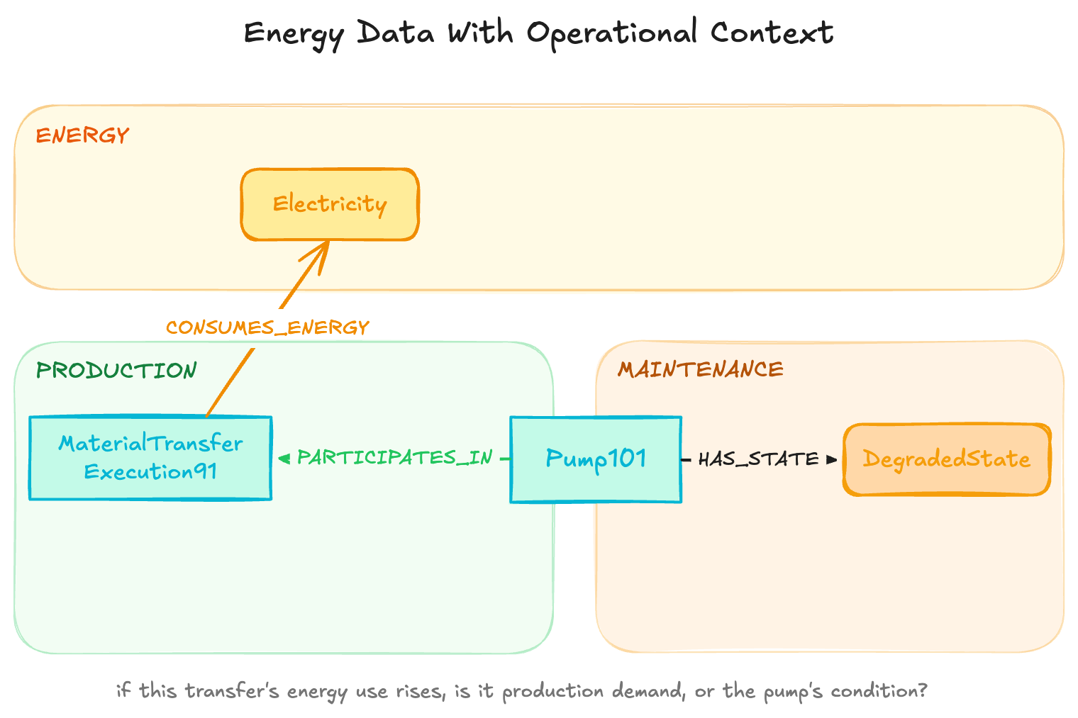
The graph can now connect energy consumption with the process, equipment, product, and production order responsible for that consumption.
An AI agent could therefore ask:
Which production process consumed the most energy per tonne of product?
or:
Which production loads could be delayed during the current peak tariff period without affecting the active production order?
Maintenance can provide further context.
Suppose a pump participates in a material-transfer process:
Pump101 PARTICIPATES_IN MaterialTransferExecution91
MaterialTransferExecution91 CONSUMES_ENERGY Electricity
Pump101 HAS_STATE DegradedStateIf the energy required for that transfer begins to increase, an application can examine whether the change is caused by production demand or by deteriorating equipment condition.
This creates a cross-domain path such as:
Energy consumption → Production process → Equipment → Maintenance condition
The energy data is no longer just a time series from a meter. It becomes part of the operational context of the plant.
Conclusion
The energy ontology extends the core manufacturing ontology with the vocabulary needed to describe how plant utilities are generated, measured, consumed, priced, and managed.
It introduces utility equipment, energy carriers, metering points, energy-management processes, tariffs, demand charges, capabilities, events, and pricing-period states. Relationships such as CONSUMES_ENERGY connect consumption directly to operational processes, while METERED_BY connects those processes and carriers to the devices that measure them.
But the central principle remains the same.
The core ontology defines the shared structure of manufacturing operations. The energy ontology adds the concepts required to understand where energy is being consumed, what that consumption costs, and how it relates to actual plant operations.
Because those concepts remain grounded in the shared core, energy can be connected directly to production, equipment condition, materials, and orders within the same manufacturing Knowledge Graph rather than remaining isolated in utility meters and monthly reports.
Get the Next Guide
New architecture guides, implementation tutorials and use-case blueprints, delivered as they’re published.
More guides
All guides →

The leading IIoT & AI educational platform for digital manufacturing teams